IM 253401-01E
3-9
3
Before Operation
3.6 Wiring the Measurement Circuit when Using
the External Sensor
WARNING
• Use an external sensor that is enclosed in a case which has sufficient
withstand voltage against the voltages to be measured. Use of bare sensor
may cause an electric shock if the sensor is touched accidentally.
• Before connecting an external shunt, make sure the power to the shunt is
turned OFF. Always make sure to turn OFF the power switch of the source.
When the power is supplied a voltage will be present at the shunt, so don't
touch the shunt with your hands.
• When using the clamp sensor, make sure to fully understand the
specifications/instruction manual regarding voltages of the measurement
circuit and the clamp sensor, and verify that no hazard exists.
• Do not touch the current terminal of the input element and not connect any
measurement lead. When power is applied to the measurement circuit, a
voltage will be generated at the current terminal, which constitutes a
hazard.
• The connector to the input terminal for the external sensor should not have
bare wires protruding; make sure to make connections to this terminal
according to safety measures, since voltages will be present at the bare
wires, which constitutes a hazard.
CAUTION
• A load current flow in the thick lines shown in the diagrams; therefore, a
wire with sufficient current capacity must be used for these lines.
Note
• The external sensor must be selected carefully and its frequency and phase characteristics taken into
account.
• The external sensor must be wired so that the area between the wires connected to both ends of the
sensor is minimized, in order to reduce the effect of the magnetic field generated by the current to be
measured. Measurement is affected by field lines entering this area. Minimizing this area also reduces
the effects of external noise.
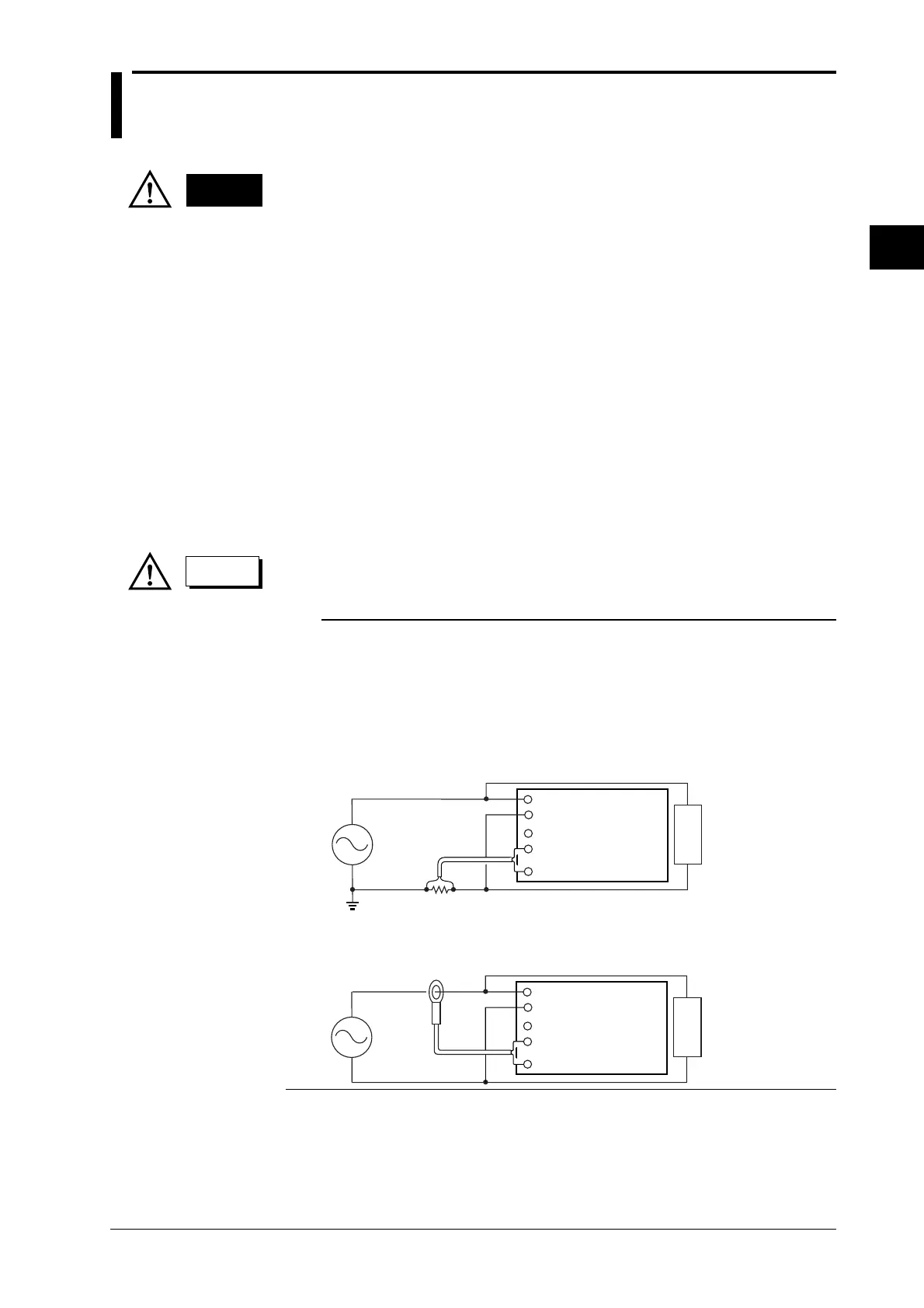
• Connect the external shunt as in the figures below. To avoid the effects of common-mode voltage, the
external shunt must be connected using AWG18 wires (cross sectional area of 1mm
2
).
• Since measurement accuracy decreases as an effect of an increase of wiring resistance and floating
capacity, keep the wiring between the external sensor and this instrument as short as possible.
LOAD
Ext. shunt
V
±
A
±
Ext. sensor input terminal
Current input terminal
Voltage input terminal
• If the measuring object is high frequency and high power and is not grounded, use an isolation sensor
(CT, DC-CT, clamp)
LOAD
Clamp sensor
V
±
A
±
Ext. sensor input terminal
Current input terminal
Voltage input terminal

 Loading...


