IM 253401-01E
3-10
In cases where the maximum current of the object under measurement exceeds 20A,
measurement becomes possible by connecting an external sensor. The range for external sensor
input is either 2.5/5/10V or 50/100/200mV. Either range is available as an option.
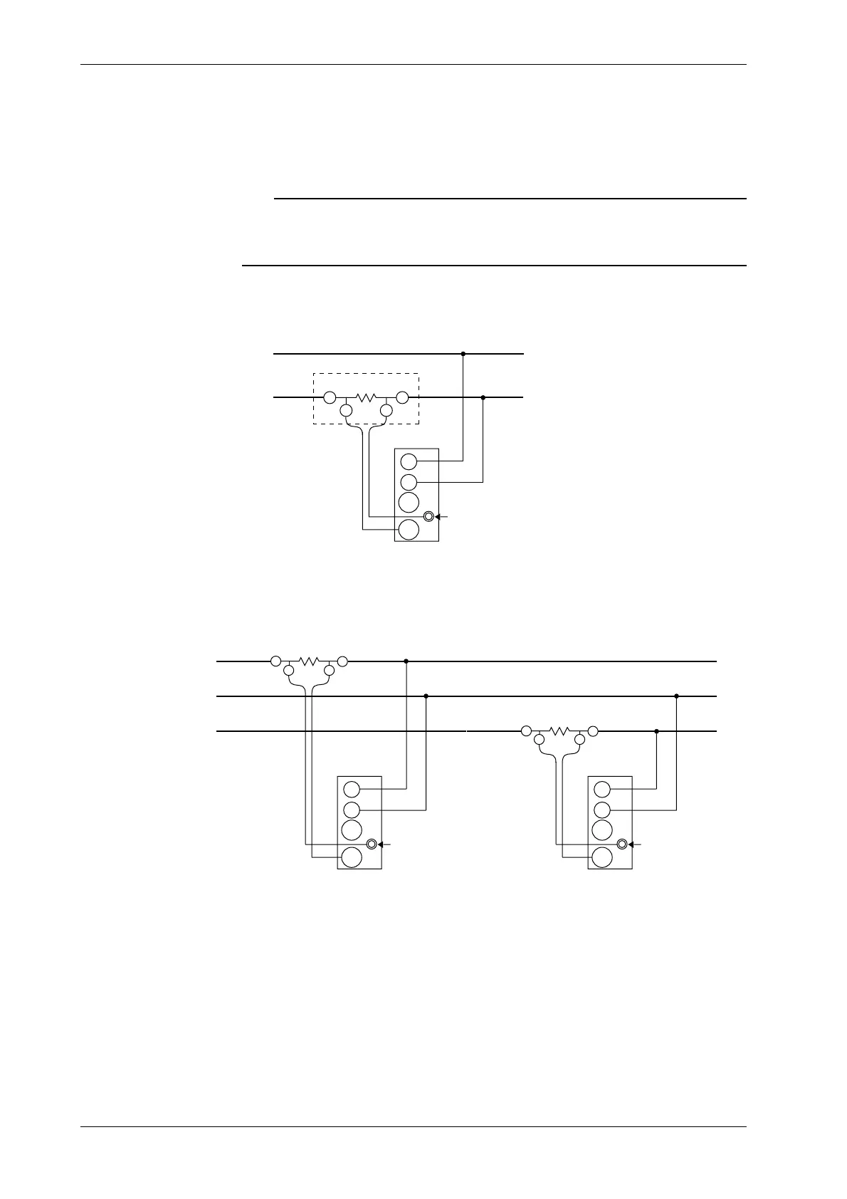
In the following wiring diagrams, the external shunt is grounded. When using the clamp sensor,
replace the shunt with the clamp sensor.
Note
• When using the external sensor or the clamp sensor, take care not to reverse the polarity when applying
the clamp to the measurement circuit.
• Using the scaling function enables direct reading of measured values on the display. Refer to section 4.5
on page 4-8.
Wiring diagram for single-phase, two-wire system with external shunt
connected (253401, 253502, 253503)
SOURCE
LOAD
Connection
side
Ext. shunt
± A
OUT L OUT H
Ext. sensor input
terminal (EXT)
A
V
±
±
Input terminal
(ELEMENT)
Wiring diagram for single-phase, three-wire system with external shunt
connected (253502, 253503)
SOURCE LOAD
±A
OUT LOUT H
±A
OUT L
OUT H
N
Ext. sensor input
terminal (EXT)
A
V
±
±
Input terminal
(ELEMENT3)
Ext. sensor input
terminal (EXT)
A
V
±
±
Input terminal
(ELEMENT1)
3.6 Wiring the Measurement Circuit when Using the External Sensor

 Loading...


