App-2
IM WT310E-01EN
• Time
u(n) • i(n)
WP
WP+
WP–
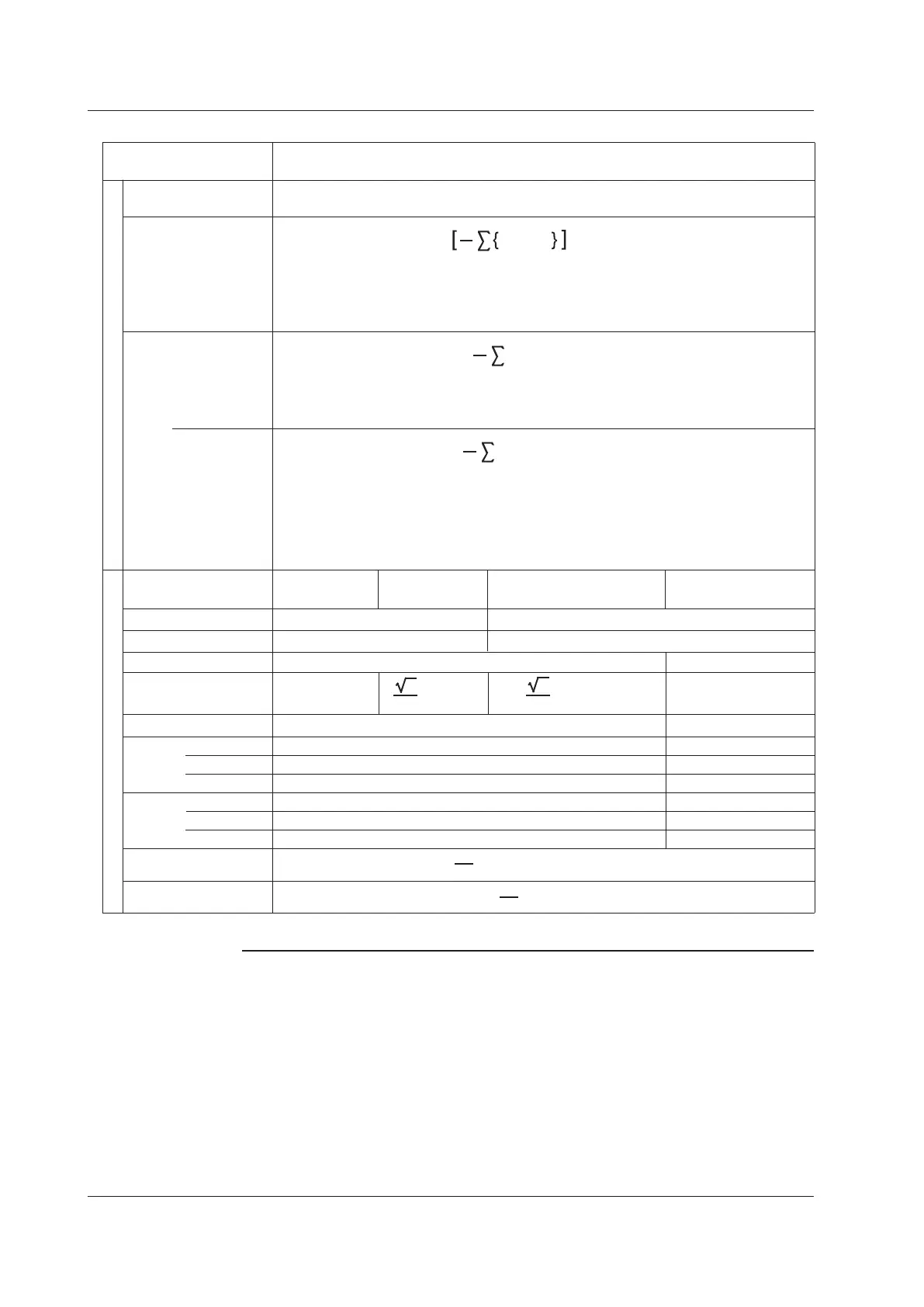
Measurement Function
Watt
hours
[Wh]
Methods of Computation and Determination
For information about the symbols in the equations see the notes.
q
q+
q–
Integration time
[h:m:s]
Time
Time from integration start to integration stop
(Table 2/2)
Single-phase,
three-wire 1P3W
Three-phase,
three-wire 3P3W
Three-voltage, three-
current measurement 3V3A
Three-phase,
four-wire 3P4W
P1 + P2 + P3
PΣ [W]
P1 + P3
UΣ [V]
Wiring system
(U1 + U3) / 2
(I1 + I3) / 2
(U1 + U2 + U3) / 3
(I1 + I2 + I3) / 3
S1 + S3
(S1 + S2 + S3)
3
3
(S1 + S3)
2
3
SΣ [VA]
S1 + S2 + S3
Q1 + Q3
QΣ [var]
Q1 + Q2 + Q3
Ampere
hours
[Ah]
rms
dc
I(n) is the nth measured current value.
N is the number of data updates.
The unit of time is hours.
I(n) • Time
n = 1
N
1
N
N is the integration time sampling count. The unit of Time is hours.
WP is the sum of positive and negative watt hours.
WP+ is the sum of the above equations for all iterations where u(n) • i(n) is positive.
WP– is the sum of the above equations for all iterations where u(n) • i(n) is negative.
i(n) • Time
n = 1
N
1
N
i(n) is the nth sampled data of the current signal.
N is the number of data samples.
The unit of time is hours.
q is the sum of i(n)'s positive and negative ampere hours.
q+ is the sum of the above equations for all iterations where i(n) is positive.
q– is the sum of the above equations for all iterations where i(n) is negative.
n = 1
N
1
N
IΣ [A]
COS
-1
(
)
PΣ
SΣ
WP
Σ
[Wh]
qΣ [Ah]
W
P
Σ
WP1 + WP3
WP1 + WP2 + WP3
λΣ
ΦΣ [°]
PΣ
SΣ
qΣ
q1 + q3
q
1 + q2 + q3
WP–1 + WP–3
WP+1 + WP+3
WP–1 + WP–2 + WP–3
WP+1 + WP+2 + WP+3
W
P
–Σ
W
P
+Σ
q–Σ
q+Σ
q
–1 + q–2 + q–3
q+1 + q+2 + q+3
q–1 + q–3
q+1 + q+3
Integration
Σ functions
Note
• u(n)denotesinstantaneousvoltage.
• i(n)denotesinstantaneouscurrent.
• ndenotesthenthmeasurementperiod.Themeasurementperiodisdeterminedbythesynchronization
source setting.
• AVG[]denotesthesimpleaverageoftheiteminbracketsdeterminedoverthedatameasurement
interval. The data measurement interval is determined by the synchronization source setting.
• PΣdenotestheactivepowerofwiringunitΣ.InputelementsareassignedtowiringunitΣdifferently
depending on the number of input elements that are installed in this instrument and the selected wiring
system pattern.
• Thenumbers1,2,and3usedintheequationsforUΣ,IΣ,PΣ,SΣ,QΣ,WPΣ,andqΣindicatethecase
when input elements 1, 2, and 3 are set to the wiring system shown in the table.
Appendix 1 Symbols and Determination of Measurement Functions

 Loading...


