2-1
IM WT310E-01EN
Measurement Conditions
2
2.1 Setting the Measurement Mode
Procedure
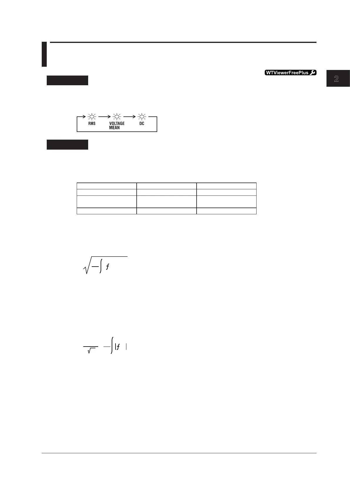
Press SHIFT+VOLTAGE (MODE) to select the measurement mode.
EachtimeyoupressSHIFT+VOLTAGE(MODE),themeasurementmodechangesintheordershown
below.
Explanation
Measurement Mode
One of the following measurement modes can be selected for the measurement of voltage and current.
ThedefaultsettingisRMS.
Indicator Voltage Current
RMS True rms value True rms value
VOLTAGEMEAN Rectifiedmeanvalue
calibrated to the rms value
True rms value
DC Linear average Linear average
Theoretical Equations
RMS
Select this mode to display the true rms values of the voltage and current.
1
(t)
2
dt
f(t) : Input signal
T : One period of the input signal
VOLTAGE MEAN
Select this mode to display the voltage as a rectified mean value calibrated to the rms value. A sine
wave is used to calibrate the value to the rms value, so when sine waves are measured, the values
obtainedinthismodearethesameasthoseobtainedinRMSmode.Thevaluesdifferfromthose
obtainedinRMSmodewhenwavesotherthansinewaves,suchasdistortedwavesandDCwaves,
are measured.
T
1
(t)
dt
f(t) : Input signal
T : One period of the input signal
2 2
·
π
DC
Select this mode when the input voltage or current is DC. The input signal is linearly averaged, and the
result is displayed.
Chapter 2 Measurement Conditions

 Loading...


