6-6
IM WT310E-01EN
6.3 Setting the PLL Source, Measured Harmonic
Order, and THD Equation
Procedure
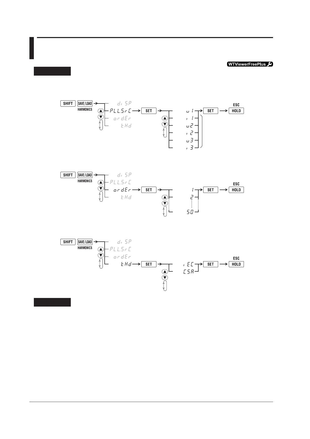
Follow the procedure indicated by the thick lines in the following menu.
PLL Source
An example for the WT333E
The display varies depending
on the installed elements.
3.
5.
Set the PLL source.
2.
4.
Confirm
the setting.
Close menu.
(Display C)
6.
Measured Harmonic Order
3.
5.
Set the harmonic order.
2.
4.
Confirm
the setting.
(Display C)
6.
THD Equation
3.
5.
Set the equation.
2.
4.
Confirm
the setting.
(Display C)
6.
Explanation
PLL Source
Set the PLL (Phase Locked Loop; frequency synchronization) source, which is used to determine the
fundamental frequency. The fundamental frequency is the reference for the measured harmonics of
harmonic measurement. The default value is U1.
Besuretospecifyasignalwiththesameperiodastheharmonicmeasurementsourcewaveform.
Selecting an input signal with small distortion and fluctuation for the PLL source will enable stable
harmonic measurement.
• U1:ThePLLsourceissettothevoltageofelement1.
• I1:ThePLLsourceissettothecurrentofelement1.
• U2:ThePLLsourceissettothevoltageofelement2(WT333Eonly).
• I2:ThePLLsourceissettothecurrentofelement2(WT333Eonly).
• U3:ThePLLsourceissettothevoltageofelement3(WT332EandWT333E).
• I3:ThePLLsourceissettothecurrentofelement3(WT332EandWT333E).

 Loading...


