App-12
IM WT310E-01EN
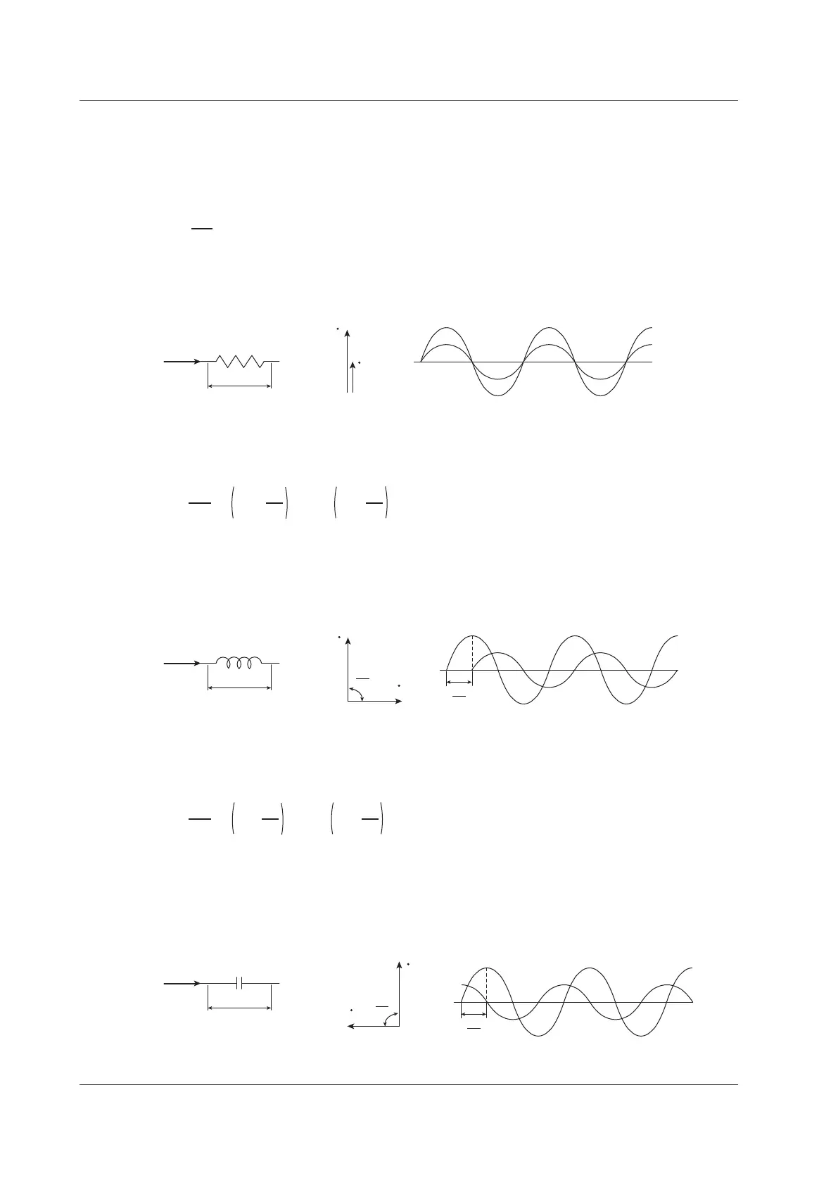
AC RLC Circuits
Resistance
ThecurrentiwhenanACvoltagewhoseinstantaneousvalueu=Umsinωtisappliedtoload
resistanceR[Ω]isexpressedbytheequationbelow.I
m
denotes the maximum current.
i =
m
R
sin
ωt
= I
msinωt
Expressedusingrmsvalues,theequationisI=U/R.
There is no phase difference between the current flowing through a resistive circuit and the voltage.
R
I
U
U
I
i
Inductance
ThecurrentiwhenanACvoltagewhoseinstantaneousvalueu=Umsinωtisappliedtoacoilloadof
inductanceL[H]isexpressedbytheequationbelow.
i =
Um
XL
sin ωt – sin ωt –
π
2
= I
m
π
2
Expressedusingrmsvalues,theequationisI=U/X
L
. X
L
is called inductive reactance and is defined
as X
L
=ωL.TheunitofinductivereactanceisΩ.
Inductance works to counter current changes (increase or decrease), and causes the current to lag the
voltage.
L
I
U
U
I
π
2
i
u
π
2
Capacitance
ThecurrentiwhenanACvoltagewhoseinstantaneousvalueu=UmsinωtisappliedtocapacitanceC
[F]isexpressedbytheequationbelow.
i =
m
XC
sin ωt + sin ωt +
2
= I
m
2
Expressedusingrmsvalues,theequationisI=U/X
C
. X
C
is called capacitive reactance and is defined
as X
C
=1/ωC.TheunitofcapacitivereactanceisΩ.
When the polarity of the voltage changes, the largest charging current with the same polarity as the
voltage flows through the capacitor. When the voltage decreases, discharge current with the opposite
polarity of the voltage flows. Thus, the current phase leads the voltage.
C
I
U
U
I
π
2
i
π
2
Appendix 2 Power Basics (Power, harmonics, and AC RLC circuits)

 Loading...


