4-2
IM WT310E-01EN
Continuous Maximum Allowable Input
Voltage
Peakvoltageof1.5kVorrmsvalueof1.0kV,whicheverisless.
Current
Direct Input
• WT310E/WT332E/WT333E
Whenthecrestfactoris3:0.5Ato20A
Whenthecrestfactoris6or6A:0.25Ato10A
Peak value of 100 A or rms value of 30 A, whichever is less.
• WT310E
Whenthecrestfactoris3:5mAto200mA
Whenthecrestfactoris6or6A:2.5mAto100mA
Peak value of 30 A or rms value of 20 A, whichever is less.
• WT310EH
When the crest factor is 3: 1 A to 40 A
Whenthecrestfactoris6or6A:0.5Ato20A
Peak value of 100 A or rms value of 44 A, whichever is less.
External Current Sensor Input
Peakvaluelessthanorequalto5timesthemeasurementrange
Maximum Displayed Value, Units, and Unit Prefixes
• Maximumdisplayedvalue:99999forvoltage,current,andactivepower(whenthenumberof
displayeddigitsissetto5)
• Units:Vforvoltage,Aforcurrent,andWforactivepower
• Unitprefix:m,k,orM
Input Element (WT332E/WT333E only)
The elements that you can select vary depending on the model. Check the model when selecting
elements.
• 1,2,or3:Displaythemeasuredvaluesofelement1,2,or3.
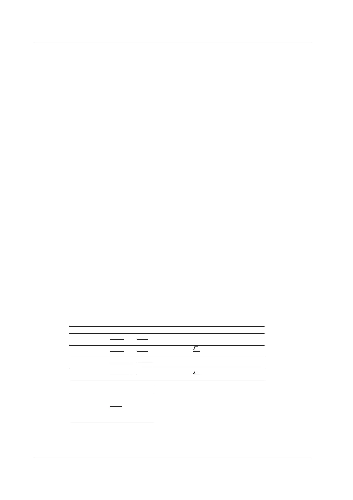
• Σ:Thedisplayedvaluesvaryasindicatedbelowdependingonthedisplayedfunctionandthewiring
system.
Wiring System UΣ IΣ
PΣ
1P3W
2
U1+U3
U1+U3
2
I1+I3
P1+P3
P1+P3
P1+P2+P3
P1+P3
2
3
U1+U2+U3
3
U1+U2+U3
U1I1+U3I3
U1I1+U2I2+U3I3
U1I1+U3I3
Q1+Q3
Q1+Q3
Q1+Q2+Q
Q1+Q3
U1I1+U2I2+U3I3
3P4W
3V3A
3P3W
2
I1+I3
2
3
3
3
I1+I2+I3
3
I1+I2+I3
(
)
3
( )
SΣ QΣ
Wiring System λΣ ΦΣ
1P3W
3P4W
3V3A
3P3W
PΣ
SΣ
cos
-1
λΣ
4.1 Displaying Voltages, Currents, and Active Powers

 Loading...


