78
YORK INTERNATIONAL
FORM 150.52-NM2 (1001)
Technical Data
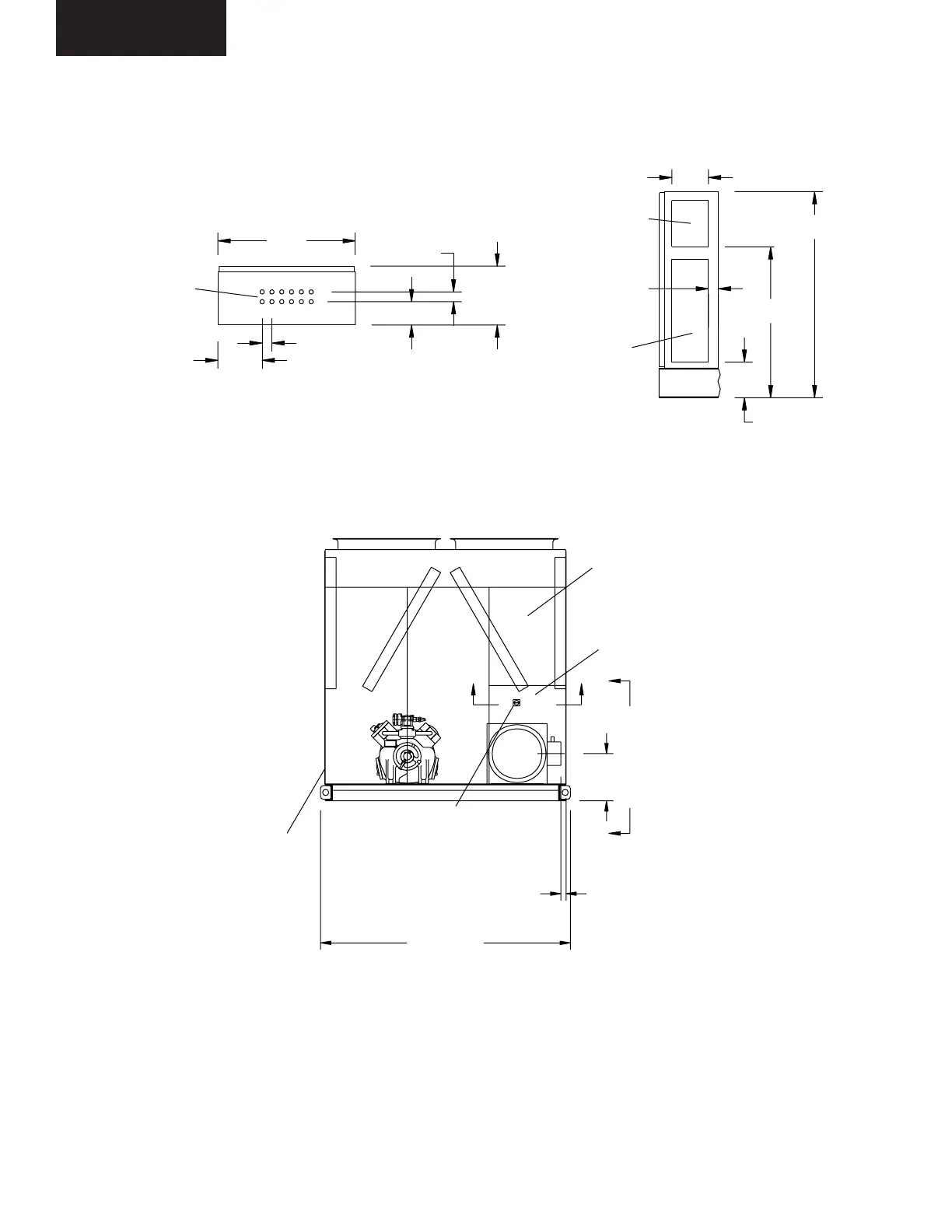
VIEW A-A
POWER OPENING
(178 WIDE x
533 TALL)
CONTROL
TRANSFORMER
SERVICE SWITCH
2321
48 (EDGE OF
UNIT TO COOLER
CONNECTION)
438
C
C
BB
OPTIONS PANEL
MICRO-COMPUTE
CONTROL CENTE
SYS. #1
COILS
SYS. #2
COILS
DO NOT USE
nless 2-compressor
unit with multiple
point power
ONTROL ENTRY
(12) 13
CONDUIT K.O.'S
229
51 TYP.
121
305
51
711
VIEW B-B
CONTROL
OPENING
(241 HIGH)
50
POWER
OPENING
(533 HIGH)
178
800
191
106
VIEW C-C
LD03544
LD03543
DIMENSIONS – YCAR 0315SC – YCAR0415SC (SI)
All dimensions
are in mm unless
otherwise noted.
NOTES:
1. Placement on a level surface free of obstructions (including snow, for winter operation) or air recirculation ensures rated performance,
reliable operation and ease of maintenance. Site restrictions may compromise minimum clearances indicated below, resulting in unpre-
dictable air flow patterns and possible diminished performance. YORK's unit controls will optimize operation without nuisance high pres-
sure safety cutout; however, the system designer must consider potential performance degradation. Access to the unit control center
assumes the unit is no higher than on spring isolators. Recommended minimum clearances: Side to wall - 2m; rear to wall - 2m; control
panel end to wall - 1.2m; top - no obstructions allowed; distance between adjacent units - 3m. No more than one adjacent wall may be
higher than the unit.
(It is recommended that power wiring enters on the right side. If left entry is used,
be sure that space is available for large wire bending radius.)
 Loading...


