JOHNSON CONTROLS
132
FORM 150.73-NM1
ISSUE DATE: 09/04/2020
SECTION 8 – UNIT OPERATION
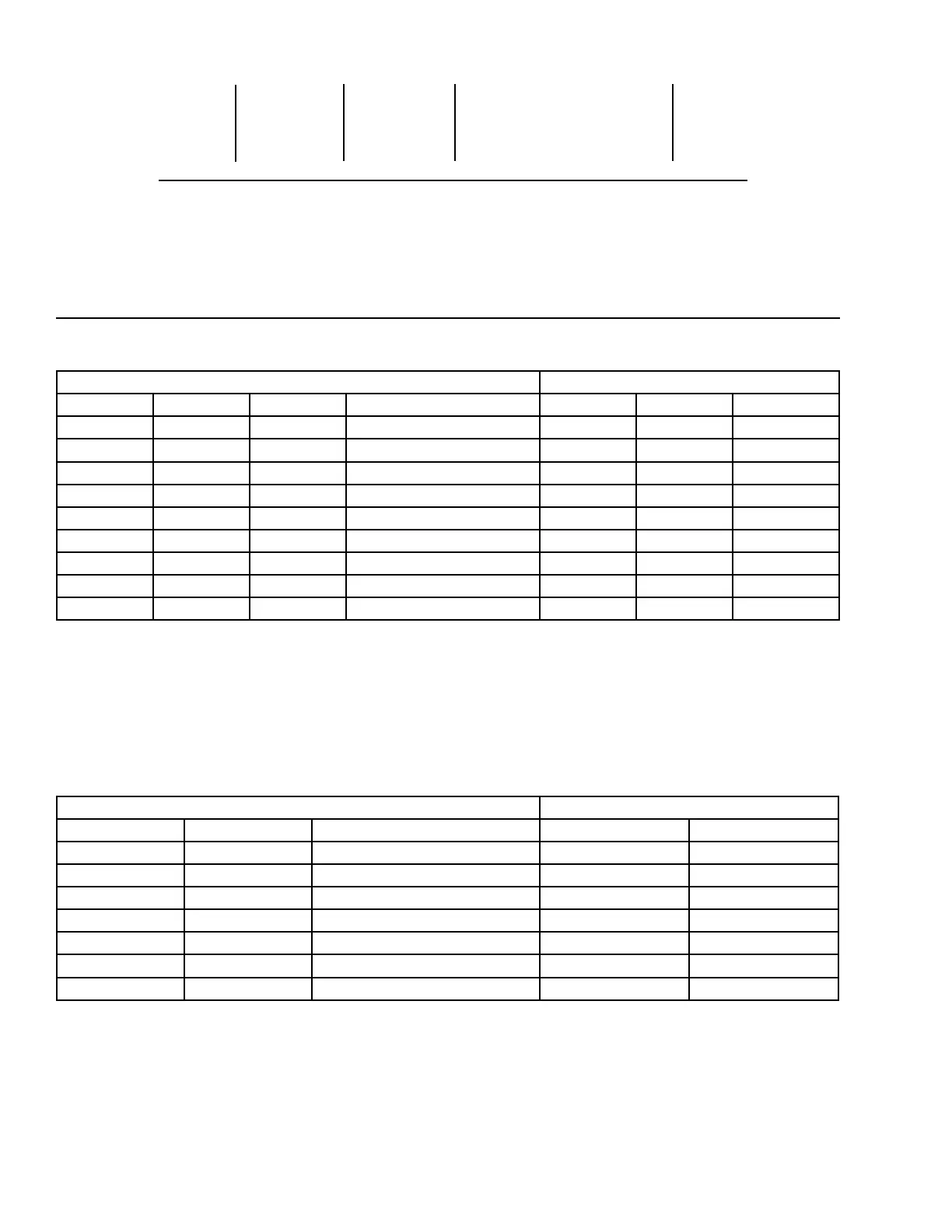
FIGURE 23 - DISCHARGE AIR TEMPERATURE CONTROL
20 sec. 30 sec. 60 sec. control range 60 sec.
unloading unloading unloading (no compressor staging) loading
51.5°F 52.5°F 53.0°F 55.0°F 57.0°
(10.8°C) (11.4°C) (11.7°C) (12.8°C) (13.9°C)
Low Limit Setpoint High limit
Discharge Air Temperature Control – Compressor Staging
Setpoint = 55.0°F (12.8°C) Range = +/- 5°F (-12.2°C)
TABLE 23 - DISCHARGE AIR TEMPERATURE CONTROL FOR 5 AND 6 COMPRESSORS (7 AND 8 STEPS)
LEAD SYSTEM (SEQUENCE - SEE NOTE 4) LAG SYSTEM (SEQUENCE - SEE NOTE 4)
* STEP COMP 1 COMP 2 COMP 3 COMP 1 COMP 2 COMP 3
0 OFF OFF OFF OFF OFF OFF
1 ON+HG OFF OFF SEE NOTE 1 OFF OFF OFF
2 ON OFF OFF OFF OFF OFF
3 ON OFF OFF SEE NOTE 2 ON OFF OFF
4 ON ON OFF SEE NOTE 3 OFF OFF OFF
5 ON ON OFF ON OFF OFF
6 ON ON OFF ON ON OFF
7 ON ON ON ON ON OFF
8 ON ON ON ON ON ON
Notes:
1. Step 1 is Hot Gas Bypass and is skipped when loading occurs. Hot Gas Bypass operation is inhibited during Pumpdown. For Discharge Air
Temperature Control the Hot Gas Bypass solenoid is energized only when the lead compressor is running and the DAT < SP, the Hot Gas
Bypass solenoid is turned o when the DAT > SP + CR/2.
2. Step 3 is skipped when loading occurs.
3. Step 4 is skipped when unloading occurs.
* STEP can be viewed using the OPER DATA key and scrolling to COOLING DEMAND.
4. Each system will attempt to rotate the lead compressor start sequence to help even out the run hours in a system, therefore piping suction
risers should be sized o the smallest compressor capacity in either system.
TABLE 24 - DISCHARGE AIR TEMPERATURE CONTROL FOR 4 COMPRESSORS (6 STEPS)
LEAD SYSTEM (SEQUENCE - SEE NOTE 4) LAG SYSTEM (SEQUENCE - SEE NOTE 4)
* STEP COMP 1 COMP 2 COMP 1 COMP 2
0 OFF OFF OFF OFF
1 ON+HG OFF SEE NOTE 1 OFF OFF
2 ON OFF OFF OFF
3 ON OFF SEE NOTE 2 ON OFF
4 ON ON SEE NOTE 3 OFF OFF
5 ON ON ON OFF
6 ON ON ON ON
Notes:
1. Step 1 is Hot Gas Bypass and is skipped when loading occurs. Hot Gas Bypass operation is inhibited during Pumpdown. For Discharge Air
Temperature Control the Hot Gas Bypass solenoid is energized only when the lead compressor is running and the DAT < SP, the Hot Gas
Bypass solenoid is turned o when the DAT > SP + CR/2.
2. Step 3 is skipped when loading occurs.
3. Step 4 is skipped when unloading occurs.
* STEP can be viewed using the OPER DATA key and scrolling to COOLING DEMAND.
4. Each system will attempt to rotate the lead compressor start sequence to help even out the run hours in a system, therefore piping suction
risers should be sized o the smallest compressor capacity in either system.