JOHNSON CONTROLS
138
FORM 150.73-NM1
ISSUE DATE: 09/04/2020
SECTION 8 – UNIT OPERATION
CONDENSER FAN CONTROL - YLUA0148 – YLUA0158
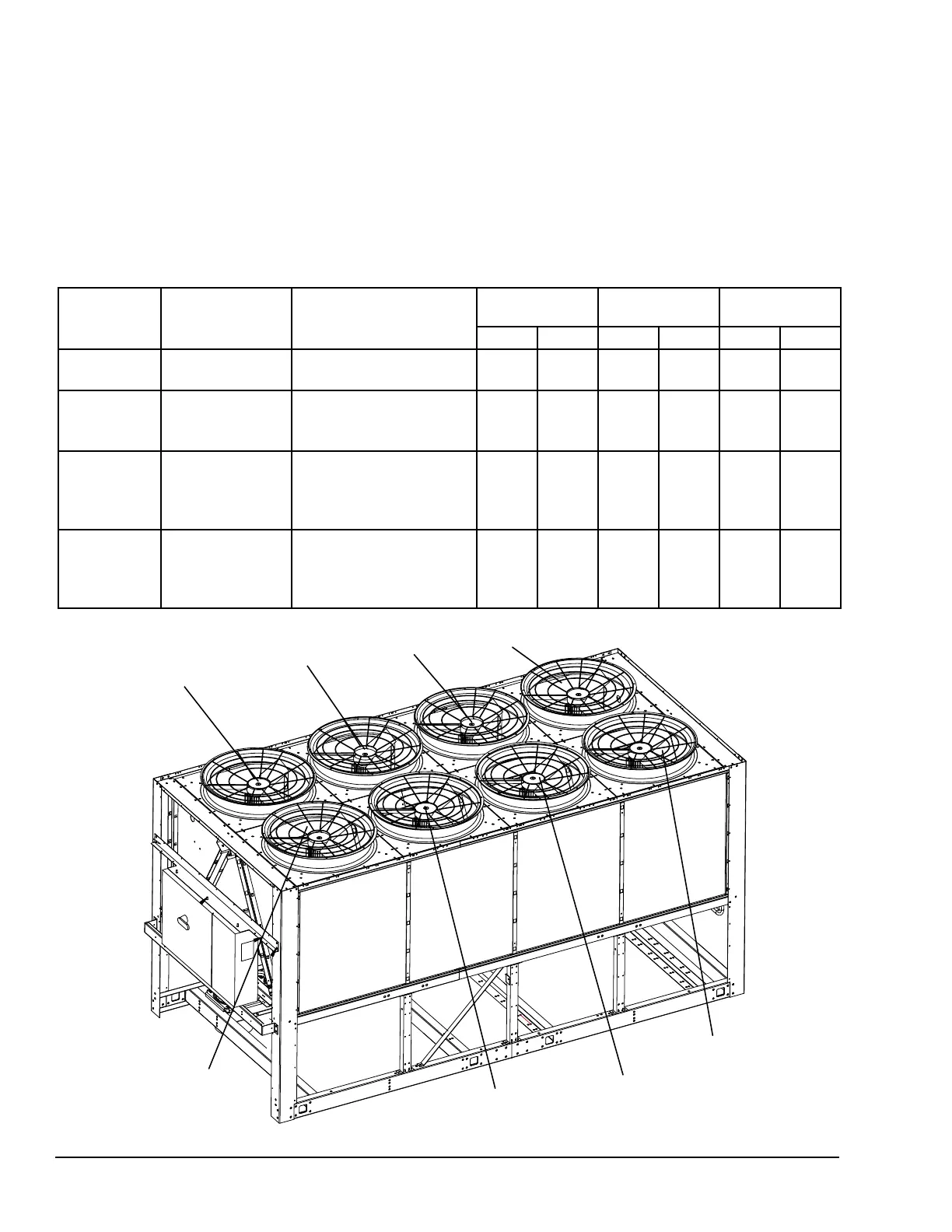
FIGURE 27 - YLUA0148 – YLUA0158 FAN LOCATION
LD14099
TABLE 29 - YLUA0148 – YLUA0158 CONDENSER FAN CONTROL
FAN
STAGE
ON OFF
CONTACTOR
MICROBOARD
OUTPUT TB-4
FAN #
SYS 1 SYS 2 SYS 1 SYS 2 SYS 1 SYS 2
1
1 FAN FWD
DP > Fan Ctrl On
Press
DP < Fan Ctrl On Press –
(Di. Press.)
10M 14M 2 6 7 8
2
2 FANS FWD
DP > Fan Ctrl On
Press + 20 psig
(1.38 Bars)
DP < Fan Ctrl On Press
– [(Di. Press.) + 20 psig
(1.38 Bars)]
9M and
10M
13M
and
14M
2 and 4 6 and 8 5 and 7 6 and 8
3
3 FANS FWD
DP > Fan Ctrl On
Press + 40 psig
(2.76 Bars)
DP < Fan Ctrl On Press
– [(Di. Press.) + 40 psig
(2.76 Bars)]
7M,
8M,
and
10M
11M,
12M
and
14M
2 and 5 6 and 9
1, 3
and 7
2, 4
and 8
4
4 FANS FWD
DP > Fan Ctrl On
Press + 60 psig
(4.14 Bars)
DP < Fan Ctrl On Press
– [(Di. Press.) + 60 psig
(4.14 Bars)]
7M,
8M,
9M,
10M
11M,
12M,
13M,
14M
2, 4
and 5
6, 8
and 9
1, 3
5, 7
2, 4
6, 8
YLUA0148 – YLUA0158 UNITS
Condenser fan control on models YLUA0148 –
YLUA0158 will always be by discharge pressure. The
on pressure and the differential off pressure are pro-
grammable under the PROGRAM key.
The following Figure and Table outlines fan sequenc-
ing for the various models. These models are equipped
to operate to 0°F ambient as a standard.
FAN #3
FAN #5
FAN #7
FAN #1
FAN #4
FAN #6
FAN #8
FAN #2