JOHNSON CONTROLS
147
SECTION 9 – SERVICE AND TROUBLESHOOTING
FORM 150.73-NM1
ISSUE DATE: 09/04/2020
9
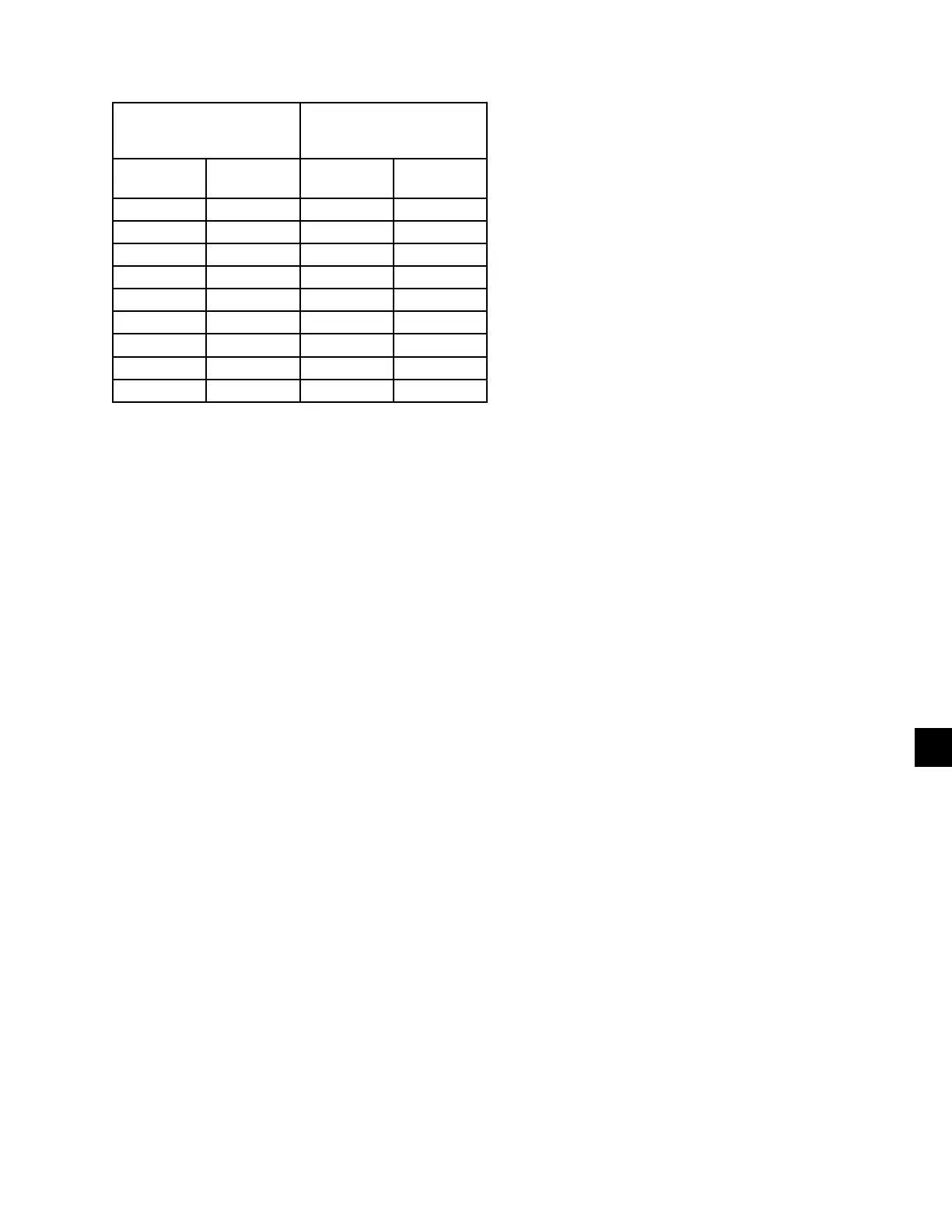
TABLE 37 - PRESSURE TRANSDUCERS
0-400 PSIG SUCTION
PRESSURE TRANS-
DUCER
0-600 PSIG DISCHARGE
PRESSURE TRANS-
DUCER
PRESSURE
PSIG
VOLTAGE
VDC
PRESSURE
PSIG
VOLTAGE
VDC
0 0.5 0 0.5
50 1.0 75 1.0
100 1.5 150 1.5
150 2.0 225 2.0
200 2.5 300 2.5
250 3.0 375 3.0
300 3.5 450 3.5
350 4.0 525 4.0
400 4.5 600 4.5
Red Wire = 5V, Black wire = 0V, White/Green Wire = signal
TEST POINTS:
Suction Pressure:
System 1:
....................................
Microboard J7-10 to J7-9
System 2:
....................................
Microboard J9-10 to J9-9
DISCHARGE PRESSURE:
System 1:
....................................
Microboard J7-11 to J7-7
System 2:
....................................
Microboard J9-11 to J9-7
V = (Pressure in psig x .01) + .5
or
V = (Pressure in BARG x .145) + .5
where V = dc voltage output
Pressure = pressure sensed by transducer
The I/O board connections for the Discharge Transduc-
ers:
System 1 Discharge Transducer
J7-6 = +5 VDC regulated supply to transducer.
J7-11 = VDC input signal to the microboard.
See the formula above for voltage readings that
correspond to specic discharge pressures.
J7-7 = +5 VDC return
J7-2 = drain (shield connection = 0 VDC)
System 2 Discharge Transducer
J9-6 = +5 VDC regulated supply to transducer.
J9-11 = VDC input signal to the microboard.
See the formula above for voltage readings that
correspond to specic discharge pressures.
J9-7 = +5 VDC return
J9-2 = drain (shield connection = 0 VDC)
The suction transducers have a range from 0 psig to
400 psig (27.5 barg). The output will be linear from 0.5
VDC to 4.5 VDC over the 400 psig (27.5 barg) range.
Following is a formula that can be used to verify the
voltage output of the transducer. All voltage reading
are in reference to ground (unit case).
V = (Pressure in psig x .02) + .5
or
V = (Pressure in barg x .29) + .5
where V = dc voltage input to micro
Pressure = pressure sensed by transducer
Following are the I/O board connections for the Suc-
tion Transducer:
System 1 Suction Transducer
J7-5 = +5 VDC regulated supply to transducer.
J7-10 = VDC input signal to the microboard.
See the formula above for voltage readings that
correspond to specic suction pressures.
J7-9 = +5 VDC return
J7-1 = drain (shield connection = 0VDC)
System 2 Suction Transducer
J9-5 = +5 VDC regulated supply to transducer.
J9-10 = VDC input signal to the microboard.
See the formula above for voltage readings that
correspond to specic suction pressures.
J7-9 = +5 VDC return
J7-11 = drain (shield connection = 0 VDC)