JOHNSON CONTROLS
135
SECTION 8 – UNIT OPERATION
FORM 150.73-NM1
ISSUE DATE: 09/04/2020
8
CONDENSER FAN CONTROL - YLUA0078 – YLUA0095
TABLE 25 - YLUA0078 – YLUA0095 CONDENSER FAN CONTROL USING OUTDOOR AMBIENT
TEMPERATURE AND DISCHARGE PRESSURE
(Discharge Pressure Controls Will Not Function Unless The Optional Discharge Pressure Transducer Is Installed)
FAN
STAGE
ON OFF
CONTACTOR
I/O BOARD
OUTPUT
FAN #
SYS 1 SYS 2 SYS 1 SYS 2 SYS 1 SYS 2
1
1 FAN
FWD
OAT >25°F (-3.9°C)
OR
DP > Fan Ctrl On Press
OAT < 20°F (-6.7°C)
AND
DP < Fan Ctrl On Press – (Di. Press.)
8M 11M TB7-9 TB10-9 3 4
*3
2 FANS
FWD
OAT >65°F (18.3°C)
OR
DP > Fan Ctrl On Press
+ 40 psig (2.76 Bars)
OAT < 60°F (15.6°C)
AND
DP < Fan Ctrl On Press.-
[Di. Press + 40 psig (2.76 Bars)]
7M
and
8M
10M
and
11M
TB7-8
and
TB7-9
TB10-8
and
TB10-9
1 and
3
2 and
4
TABLE 26 - YLUA0078 – YLUA0095 CONDENSER FAN CONTROL USING DISCHARGE PRESSURE ONLY
FAN
STAGE
ON OFF
CONTACTOR
I/O BOARD
OUTPUT
FAN #
SYS 1 SYS 2 SYS 1 SYS 2 SYS 1 SYS 2
1
1 FAN
FWD
DP > Fan Ctrl On Press DP < Fan Ctrl On Press – (Di. Press.) 8M 11M TB7-9 TB10-9 3 4
*3
2 FANS
FWD
DP > Fan Ctrl On Press
+ 40 psig (2.76 Bars)
DP < Fan Ctrl On Press.) –
[(Di Press.) + 40 psig (2.76 Bars)]
7M
and
8M
10M
and
11M
TB7-8
and
TB7-9
TB10-8
and
TB10-9
1
and
3
2
and
4
* NOTE: STEP 2 is not active in the “Standard Ambient” mode. When changing to “Low Ambient” control, fan power wiring also changes.
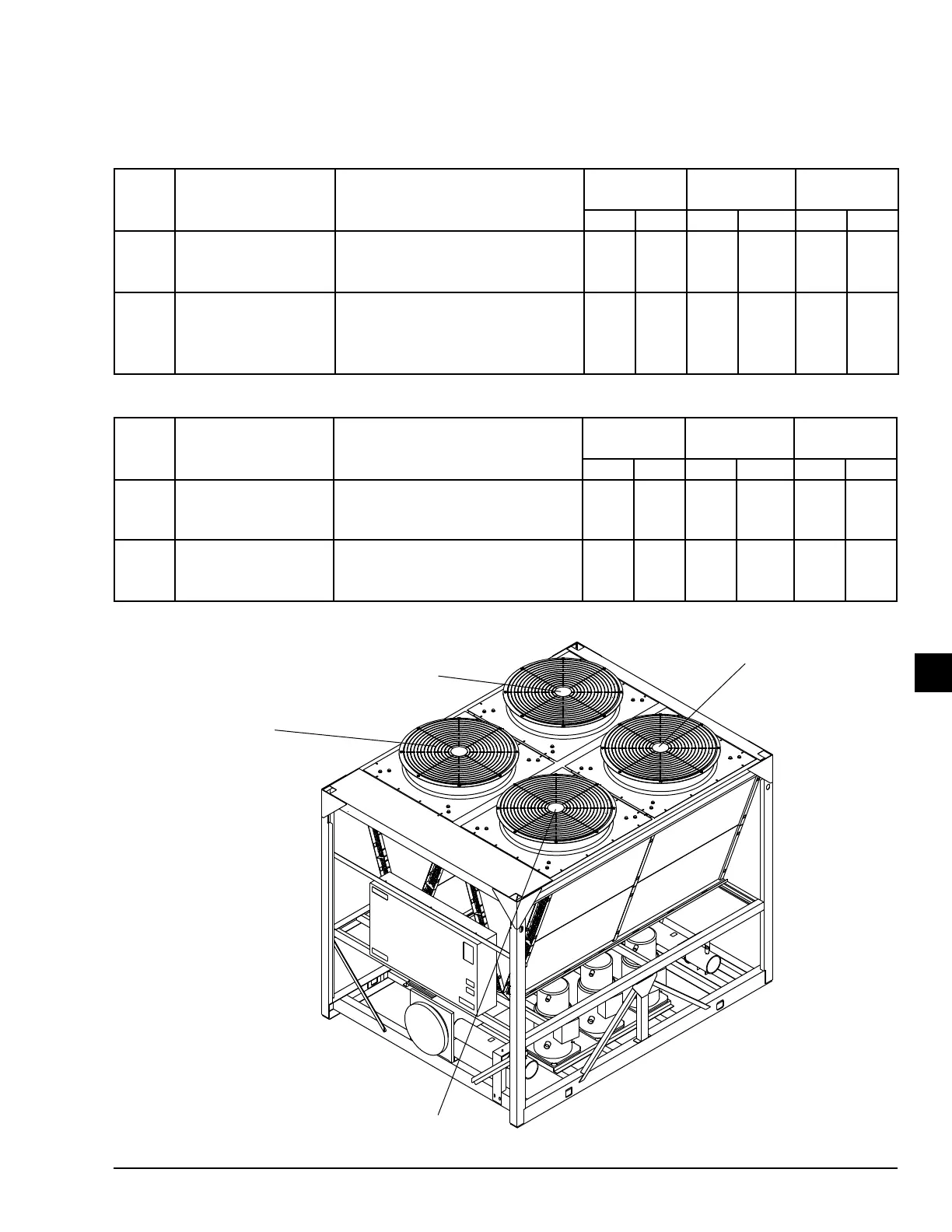
FIGURE 25 - YLUA0078 – YLUA0095 FAN LOCATION (TYPICAL)
LD07403A