JOHNSON CONTROLS
39
SECTION 4 – INSTALLATION
FORM 150.73-NM1
ISSUE DATE: 09/04/2020
4
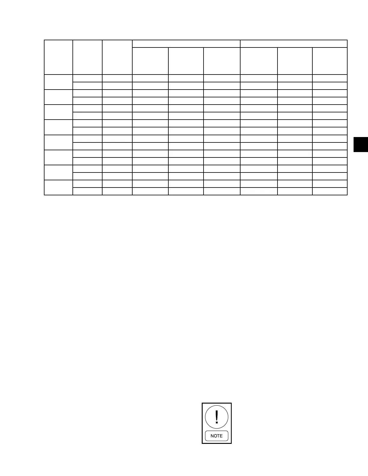
TABLE 5 - REFRIGERANT LINE PRESSURE DROPS (ENGLISH)
MODEL
NUMBER
SYSTEM
NUMBER
NOMINAL
TONS
SUCTION LINE LIQUID LINE
COPPER
TYPE L
INCHES OD
PRESSURE
DROP
PSI/100FT
VELOCITY
@ NOMINAL
CAPACITY
IN FPM
NOMINAL
TONS
UNLOADED
COPPER
TYPE L
INCHES OD
PRESSURE
DROP
PSI/100FT
0078ZE
1 40.6 2-5/8 1 1656 13.5 1-1/8 3.90
2 40.6 2-5/8 1 1656 3.5 1-1/8 3.90
0088ZE
1 44.7 2-5/8 1.2 1818 14.9 1-1/8 4.92
2 39.6 2-5/8 0.9 1572 13.2 1-1/8 3.73
0095ZE
1 44.7 2-5/8 1.2 1812 14.9 1-1/8 4.85
2 46.4 2-5/8 1.3 1896 14.9 1-1/8 5.26
0098YE
1 49.2 2-5/8 1.3 1896 14.9 1-1/8 5.21
2 49.2 2-5/8 1.3 1896 14.9 1-1/8 5.21
0108YE
1 44.4 2-5/8 1.2 1812 14.9 1-1/8 4.86
2 67.2 2-5/8 2.3 2598 33.6 1-1/8 9.26
0130ZE
1 65.5 2-5/8 2.4 2658 32.8 1-1/8 9.64
2 65.5 2-5/8 2.4 2658 32.8 1-1/8 9.64
0148ZE
1 93.9 3-1/8 2.1 2790 31.3 1-3/8 5.74
2 51.4 2-5/8 1.4 1926 14.9 1-1/8 5.28
0158ZE
1 92.1 3-1/8 2 2658 30.7 1-3/8 6.31
2 66.1 2-5/8 2.3 2556 33.1 1-3/8 8.87
REFRIGERANT PIPING NOTES
1. Based on R-22 at the nominal capacity of the unit
or system, an ambient temperature of 95°F (35°C)
and a suction temperature of 45°F (7.2 °C).
2. Suction line sizes were calculated based on a
nominal maximum pressure drop of 3 psi/100 ft
(20.7 kPa/30.5 m). When calculating suction line
pressure drop for a specic application, it should
be noted that system capacity decreases as suction
line pressure drop increases.
3. Liquid pressure drop (or gain) due to a vertical liq-
uid line is not included in the tables and must be
taken into account when determining pressure drop
(or gain) of the liquid line. The nominal value that
must be included in the liquid line loss (or gain) is
0.5 psi/foot (3.4 kPa/30 cm) of rise (or gain). To en-
sure a solid column of liquid refrigerant to the ex-
pansion valve, the total maximum pressure drop of
the liquid line should not exceed 40 psi (276 kPa)
based on 15°F (8.3 °C) subcooled liquid. Vapor in
the liquid line, even in small amounts, will mea-
surably reduce valve capacity and poor system per-
formance will result. In addition, pressure loss for
strainers, lter driers, solenoid valves, and isolation
valve or ttings are not included in this table, and
must be taken into account.
4. Nominal Tons (KW) Unloaded is based on one
compressor (per system) operating at design con-
ditions.
5. Based on minimum compressor staging for the
given pipe size, a double suction riser should be
used to ensure proper oil return to the compres-
sor on all vertical suction risers. Oil returning up
the riser moves up the inner surface of the pipe
and depends on the mass velocity of the refriger-
ant vapor at the wall surface to move the oil up
the vertical rise. Using piping of this size will al-
low velocities at part load to fall below 1000 fpm
(5.08 m/s) minimum required for oil return.
6. Hot gas bypass lines are typically 7/8 in. for lines
up to 40 ft and 1 1/8 in. for lines over 40 ft (12 m)
in length. The eld connections sizes are 7/8 in.
for the optional factory mounted hot gas bypass
valve.
7. For more information, refer to either the John-
son Controls DX Piping Application Guide or the
ASHRAE Refrigeration Handbook.
Hot gas bypass is only available for re-
frigerant system number 1.