JOHNSON CONTROLS
84
FORM 150.73-NM1
ISSUE DATE: 09/04/2020
SECTION 5 – TECHNICAL DATA
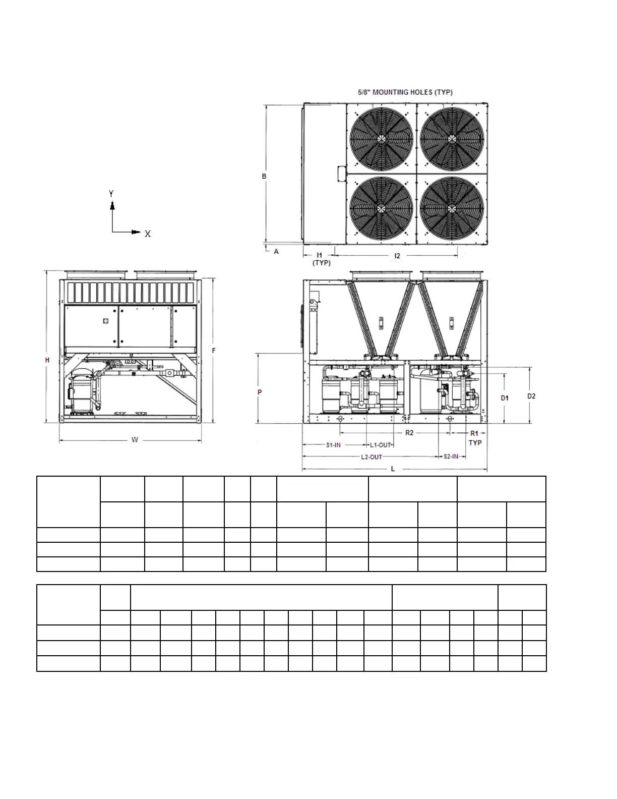
DIMENSIONS – YLUA0078 TO 0095 (ENGLISH)
DIMENSIONS (ENGLISH)
NEW
MODEL
LENGTH WIDTH HEIGHT
CONNECTION
SIZES
SYSTEM 1
DIMENSIONS
SYSTEM 2
DIMENSIONS
L W H F P
SUCTION
IN 1/2
LIQUID
OUT 1/2
SUCTION
IN
LIQUID
OUT
SUCTION
IN
LIQUID
OUT
YLUA0078ZE 116.1 88.3 95.3 89.7 43.9 2.7 1.1 39.6 17 17 84.3
YLUA0088ZE 116.1 88.3 95.3 89.7 43.9 2.7 1.1 39.6 17 17 84.3
YLUA0095ZE 116.1 88.3 95.3 89.7 43.9 2.7 1.1 39.6 17 17 84.3
NEW
MODEL
ISOLATOR LOCATION DIMENSIONS
RIGGING HOLE
LOCATIONS
UNIT
COG
D2 I1 I2 I3 I4 I5 I6 I7 I8 A B R1 R2 R3 R4 X Y
YLUA0078ZE 35.5 19.5 76.6 1.3 85.5 23.2 68.3
YLUA0088ZE 35.5 19.5 76.6 1.3 85.5 23.2 68.3
YLUA0095ZE 35.5 18.5 76.6 1.3 85.5 23.2 68.3
All Dimensions are in inches unless otherwise specied.
NOTE: Placement on a level surface free of obstructions (including snow, for winter operation) or air circulation ensures rated performance,
reliable operation, and ease of maintenance. Site restrictions may compromise minimum clearances indicated below, resulting in unpredictable
airow patterns and possible diminished performance. Johnson Controls unit controls will optimize operation without nuisance high-pressure
safety cutouts; however, the system designer must consider potential performance degradation. Access to the unit control center assumes the
unit is no higher than on spring isolators. Recommended minimum clearances: Side to wall – 6 ft; rear to wall – 6 ft; control panel to end wall
– 4 ft; top – no obstructions allowed; distance between adjacent units – 10 ft. No more than one adjacent wall may be higher than the unit.