JOHNSON CONTROLS
143
SECTION 9 – SERVICE AND TROUBLESHOOTING
FORM 150.73-NM1
ISSUE DATE: 09/04/2020
9
The digital inputs will display the input connection and
ON/OFF status such as:
F L O W S W / R E M S T A R T
J 13 - 5 I S O N
This indicates that the flow switch/remote start input is
connected to plug 13- pin 5 (J13-5) on the microboard,
and is ON (ON = +30 VDC unregulated input, OFF =
0VDC input on digital inputs).
CONTROL INPUTS/OUTPUTS
These tables are a quick reference list providing the
connection points and a description of the inputs and
outputs respectively. All input and output connections
pertain to the connections at the microboard.
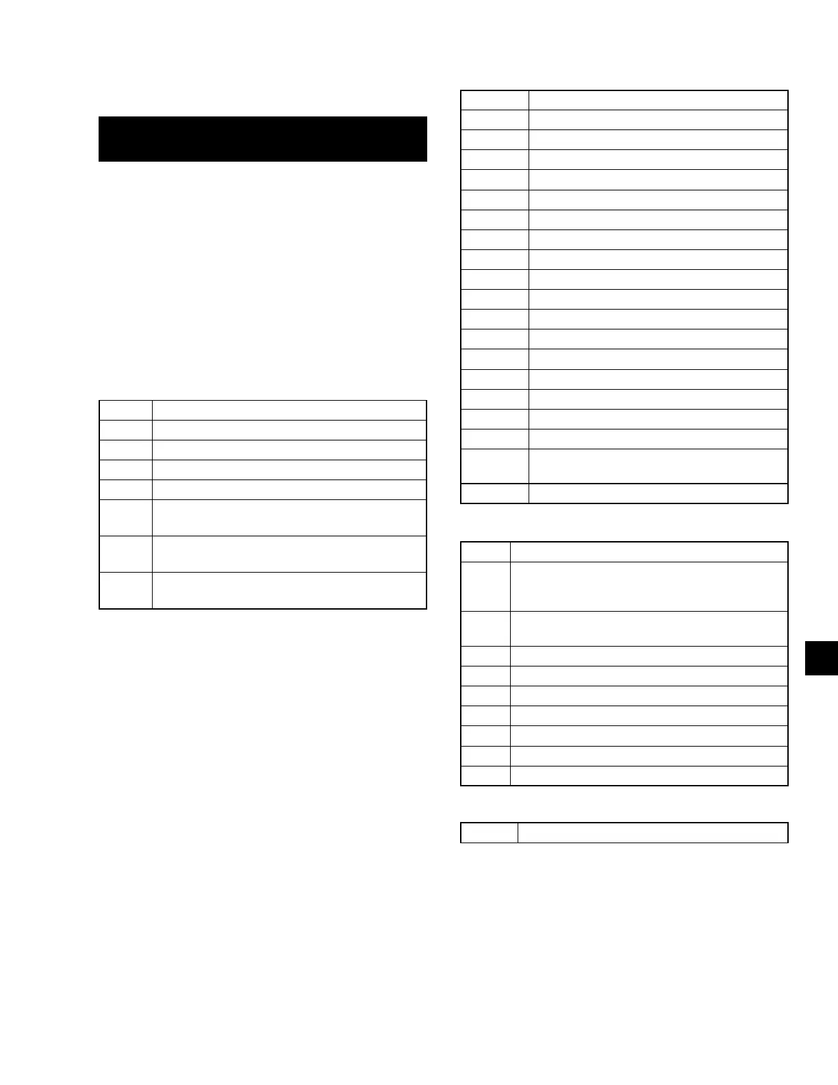
TABLE 31 - I/O DIGITAL INPUTS
J13-2 Unit ON/OFF Switch
J13-3 Load Limit Stage 2 on 3, 5 and 6 Comp. Units
J13-4 Load Limit Stage 1
J13-5 SYS 1 Zone Thermostat
J13-6 SYS 2 Zone Thermostat
J13-7
Single System Select
(Jumper = Single Sys, No Jumper = Two Sys)
J13-8
CR1
(Sys 1 Motor Protector/High Pressure Cutout)
J13-10
CR2
(Sys 2 Motor Protector/High Pressure Cutout)
TABLE 32 - I/O DIGITAL OUTPUTS
TB7-2 SYS 1 Compressor 1
TB7-3 SYS 1 Liquid Line Solenoid Valve
TB7-4 SYS 1 Compressor 2
TB7-5 SYS 1 Compressor 3
TB7-7 SYS 1 Hot Gas Bypass Valve
TB10-2 SYS 2 Compressor 1
TB10-3 SYS 2 Liquid Line Solenoid Valve
TB10-4 SYS 2 Compressor 2
TB10-5 SYS 2 Compressor 3
TB7-8 SYS 1 Condenser Fan Output 1
TB7-9 SYS 1 Condenser Fan Output 2
TB7-10 SYS 1 Condenser Fan Output 3
TB10-8 SYS 2 Condenser Fan Output 1
TB10-9 SYS 2 Condenser Fan Output 2
TB10-10 SYS 2 Condenser Fan Output 3
TB8-2 Evaporator Heater
TB8-3 SYS 1 Alarm
TB9-2 SYS 2 Alarm
TB8-6
and 7
Evaporator Pump Starter
TB10-7 SYS 2 Hot Gas Bypass Valve
TABLE 33 - I/O ANALOG INPUTS
J7-10 SYS 1 Suction Transducer
J11-12
Unit Type: Chiller = NO Jumper J11-12 to +24 VDC
YLUA Condensing Unit = Jumper J11-12 to +24 VDC
(Do NOT Use)
J7-11
SYS 1 Discharge Pressure Transducer (Op-
tional)
J6-9 Ambient Air Temp. Sensor
J6-7 Leaving Chilled Liquid Temp. Sensor (Not Used)
J6-8 Discharge Air Temp Sensor
J9-10 SYS 2 Suction Pressure Transducer
J9-11 SYS 2 Discharge Pressure Transducer
J7-12 Unit/SYS 1 Voltage
J9-12 SYS 2 Voltage
TABLE 34 - I/O ANALOG OUTPUTS
N/A Not Applicable