JOHNSON CONTROLS
148
FORM 150.73-NM1
ISSUE DATE: 09/04/2020
SECTION 9 – SERVICE AND TROUBLESHOOTING
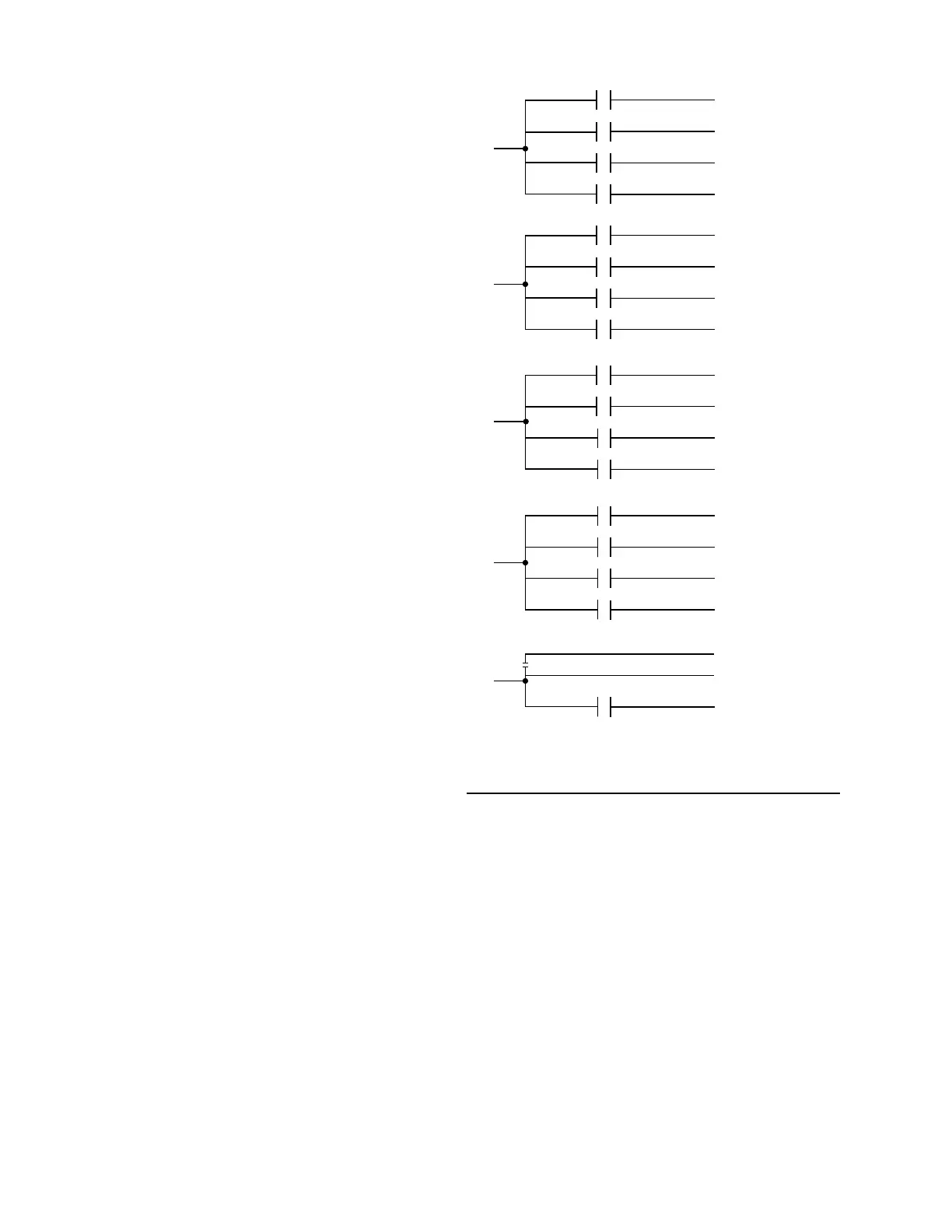
Digital Outputs
Refer to the unit wiring diagram and Figure 29 on page
148. The digital outputs are located on TB7, TB8, and
TB9 and TB-10 of the microboard. ALL OUTPUTS
ARE 120 VAC with the exception of TB8-6 to TB8-7
which are the contacts that can be used for a remote
evaporator pump start signal. The voltage applied to
either of these terminals would be determined by field
wiring.
Each output is controlled by the microprocessor by
switching 120 VAC to the respective output connection
energizing contactors, evaporator heater, and solenoids
according to the operating sequence (see Figure 29 on
page 148).
120 VAC is supplied to the I/O board via connections
at TB7-1, TB7-6, TB10-1, TB10-6, TB8-1 and TB9-1
Figure 29 on page 148 illustrates the relay contact
architecture on the microboard.
FIGURE 29 - I/O BOARD RELAY CONTACT
ARCHITECTURE
LD12722
SYS 1
COMP 1
TB7-2
SYS 1
COMP 2
TB7-4
SYS 1
COMP 3
TB7-5
TB7-3 LLSV 1
TB8-6
EVAP
PUMP
TB8-7
TB7
SYS 2
HGSV
TB10-7
SYS 2
FAN 2
TB10-8
TB10-9
TB10-10
SYS 2
FAN 4
TB10
TB8
TB10
SYS 2
COMPR 1 (4)
TB10-2
LLSV 2
TB10-3
SYS 2
COMPR 2 (5)
TB10-4
SYS 2
COMPR 3 (6)
TB10-5
TB7
SYS 1
HGSV
TB7-7
SYS 1
FAN 1
TB7-9
SYS 1
FAN 3
TB7-10
TB7-8
SYS 1
FAN 2
TB8-2
HEAT EXCH
HEATER
*
*
* Not Used