START-UP
Axiovert 200 Reflector turret Carl Zeiss
B 40-080 e 03/01 2-17
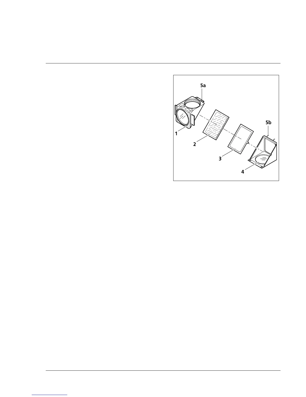
• Hold both halves of the reflector module
together, turn them around into the installation
position and put them down.
• Now tilt the upper module half (2-20/1)
upwards and lift it out of the holding elements
(2-20/5b) of the lower module half.
• Remove beam splitter (2-20/2) and spring frame
(2-20/3) from the lower module half.
• Remove old beam splitter and carefully place
the new one on the spring frame (2-20/4) with
the reflecting side pointing downwards, and
then insert both parts together in the lower
module half. Make sure that the lateral catch
of the spring frame is positioned in the relevant
recess in the lower module half.
If there is no distance between a wooden pin and
its mirror image when such a pin is carefully placed
on the surface of the beam splitter, this is the
reflecting side of the beam splitter.
• Place upper module half (2-20/1) on the lower one (2-20/4) (holding elements 2-20/5b and lugs
2-20/5a mesh with each other). Hold both halves together and turn them around into the installation
position.
• Insert and tighten slotted screws.
• Finally, attach the adhesive label with the name of the filter combination to the side of the module.
Fig. 2-20 Changing the beam splitter