OPERATION
Carl Zeiss List of illustrations Axiovert 200
3-2 B 40-080 e 03/01
List of illustrations
Fig. 3-1 Operation and function controls on the Axiovert 200 (manual).........................................3-4
Fig. 3-2 Nosepiece with mounts for DIC slider ..............................................................................3-7
Fig. 3-3 Binocular tube 45°/23 .....................................................................................................3-8
Fig. 3-4 Binocular phototube 45°/23 ............................................................................................3-8
Fig. 3-5 Setting of eyepiece distance on the binocular tube...........................................................3-9
Fig. 3-6 LCD display.....................................................................................................................3-9
Fig. 3-7 LD condenser 0.55, 6-position, H, Ph1, Ph2, Ph3, Var1/2............................................... 3-10
Fig. 3-8 LD condenser 0.35, 6-position, H, Ph0, Ph1, Ph2, DIC, DIC............................................. 3-10
Fig. 3-9 5-position reflector turret.............................................................................................. 3-13
Fig. 3-10 Iris stop slider................................................................................................................3-13
Fig. 3-11 On / Off switch and toggle switch..................................................................................3-14
Fig. 3-12 Key "Set LM"................................................................................................................ 3-14
Fig. 3-13 Operation and function controls on the Axiovert 200 M (motorized)...............................3-16
Fig. 3-14 LCD-Display...................................................................................................................3-19
Fig. 3-15 Condenser 0.55, 6-position H, Ph1, Ph2, Ph3, DIC, DIC................................................. 3-20
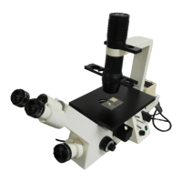
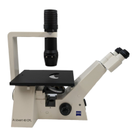
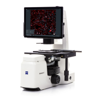
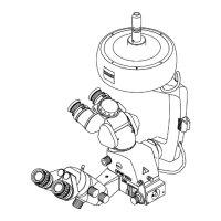
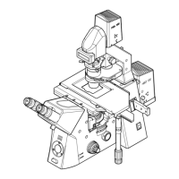
Fig. 3-16 Axiovert 200.................................................................................................................3-30
Fig. 3-17 Diaphragm settings for KÖHLER illumination in transmitted-light brightfield....................3-31
Fig. 3-18 Centering the phase stop on the condenser...................................................................3-34
Fig. 3-19 Centering of phase stop (bright in condenser) with phase ring (dark in objective)............ 3-34
Fig. 3-20 Components for the transmitted-light DIC technique on the Axiovert 200...................... 3-37
Fig. 3-21 Setting of VAREL contrast..............................................................................................3-38
Fig. 3-22 VAREL contrast with microtiter plates ............................................................................3-39
Fig. 3-23 Pupil images in VAREL contrast...................................................................................... 3-39
Fig. 3-24 Components for epi-fluorescence on the Axiovert 200................................................... 3-41
Fig. 3-25 Connection of a SLR camera..........................................................................................3-45
Fig. 3-26 Video attachment..........................................................................................................3-46