GETIING
TO KNOW YOUR TV (CONTINUED)
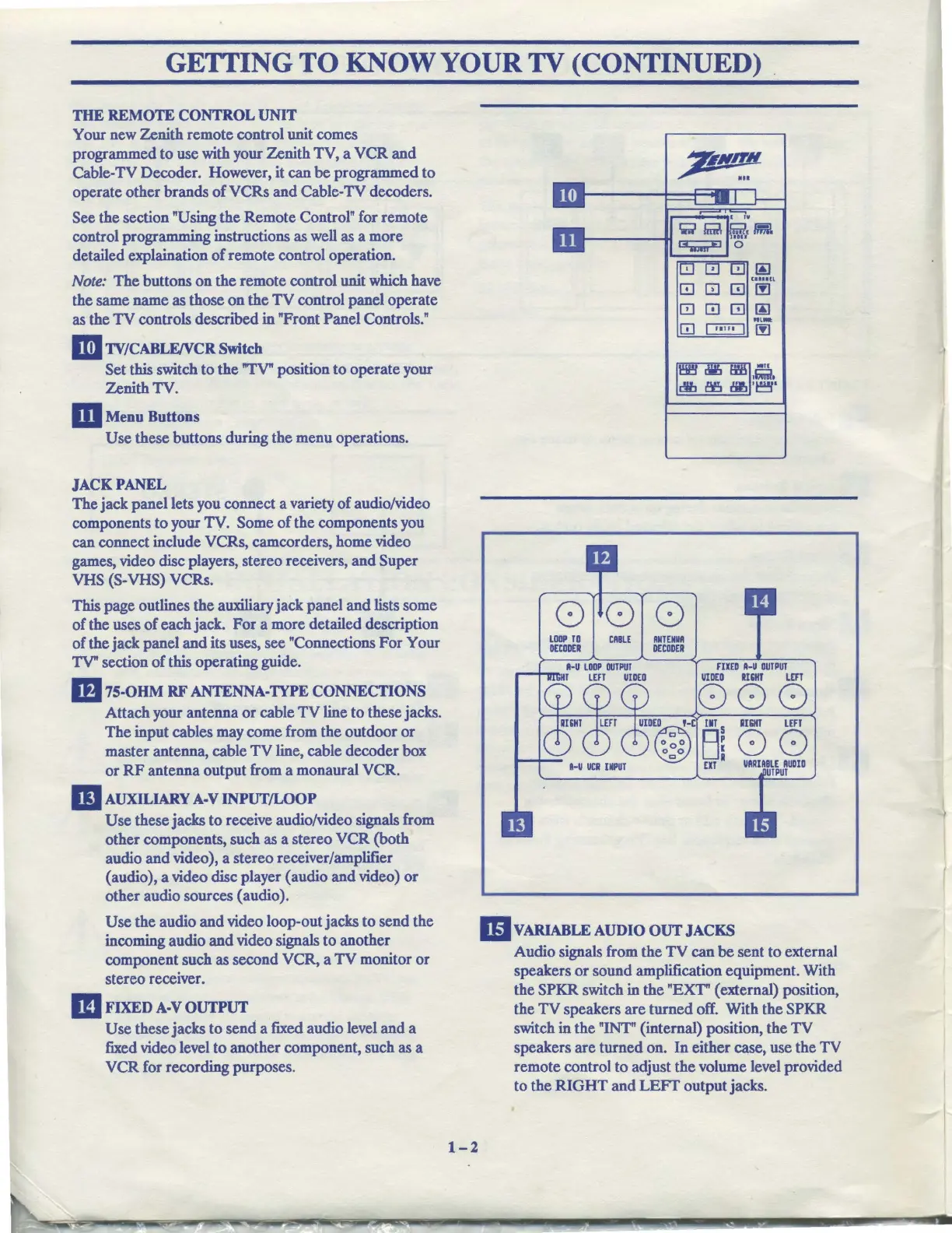
THE
REMOTE
CONTROL
UNIT
Your new Zenith remote control unit comes
programmed to use with your Zenith TV, a
VCR
and
Cable-TV Decoder. However, it can
be
programmed to
operate other brands
of
VCRs
and
Cable-TV decoders.
See the section "Using
the
Remote Control" for remote
control programming instructions as well as a more
detailed explaination
of
remote control operation.
Note:
The buttons
on
the
remote control unit which have
the same name as those
on
the
TV
control panel operate
as the
TV
controls described in "Front Panel Controls."
II!I
TV/CABLFJVCR
Switch
Set this switch
to
the
"TV" position to operate your
Zenith TV.
m Menu Buttons
Use
these buttons during the menu operations.
JACKPANEL
The jack panel lets you connect a variety
of
audio/video
components
to
your TV. Some
of
the components you
can connect include VCRs, camcorders, home video
games, video disc players, stereo receivers,
and
Super
VHS (S-VHS) VCRs.
This page outlines the auxiliary jack panel
and
lists some
of
the uses
of
each jack.
For
a more detailed description
of
the jack panel
and
its uses, see "Connections
For
Your
TV" section
of
this operating guide.
m
75-OHM
RF
ANTENNA-TYPE
CONNECTIONS
Attach your antenna
or
cable
TV
line to these jacks.
The input cables may come from the outdoor
or
master antenna, cable
TV
line, cable decoder box
or
RF
antenna output from a monaural VCR.
m
AUXILIARY
A-V
INPUT/LOOP
Use
these jacks
to
receive audio/video signals from
other components, such as a stereo
VCR
(both
audio
and
video), a stereo receiver/amplifier
(audio), a video disc player ( audio
and
video)
or
other audio sources (audio).
Use
the audio
and
video loop-out jacks to send the
incoming audio
and
video signals to another
component such as second VCR, a
TV
monitor
or
stereo receiver.
m
FIXED
A-V
OUTPUT
Use
these jacks to send a fixed audio level and a
fixed video level
to
another component, such as a
VCR
for recording purposes.
1-2
GJ
0 0 m @
"'-
[!]
~
00
000
UlllP
TO
DECODER
CABLE
ANT
EM
DECODER
FllED
A-U
OUTPUT
VIDEO
ll&IIT
LEFT
000
o~o
D~
UIDE(ill)D
,-c
llT S
oc,o
u.
EIT
II&IIT
LEFf
00
VARIABLE
AUDIO
!PUT
llvARIABLE
AUDIO
OUT
JACKS
Audio signals from the
TV
can
be
sent to external
speakers
or
sound amplification equipment. With
the SPKR switch in the "EXT" ( external) position,
the
TV
speakers
are
turned off. With the SPKR
switch in the "INT" (internal) position, the
TV
speakers are turned on.
In
either case, use the
TV
remote control to adjust the volume level provided
to the
RIGHT
and
LEFT
output jacks.