20-38 Power Pack
Power Pack
20
10. Remove both positive and negative power
leads.
NOTE: Always record quantity and fitted
position of foam spacers.
Installation
1. Installation is the reverse of removal
procedure.
Contactor [22MY Onwards]
CAUTION: Always perform the High Voltage
Discharging procedure prior to servicing any
High Voltage component or connection. Proper
procedures must be followed! To protect
electrical components, perform the following
tasks in the order given. Do not deviate from the
repair procedure processes.
NOTICE: Before carrying out any work on the
electrical system, remove the key from the key
switch.
Removal
1. Remove top cover. See Top Cover [22MY
Onwards], page 20.33.
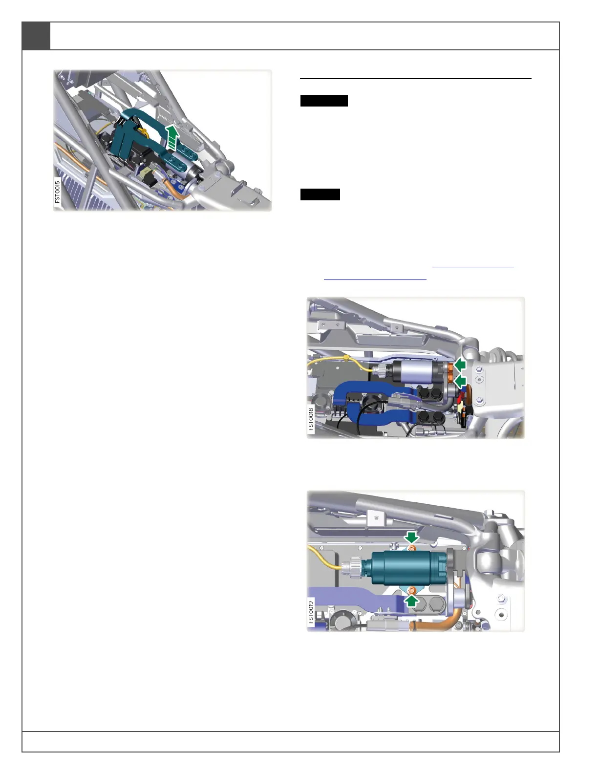
2. Remove bolts (x2) securing BCB main BUS
set to contactor. Torque 10 lb-ft (13.5 Nm).
3. Remove bolts (x2) securing contactor to
battery unit. Torque 6 lb-ft (8 Nm).