Console Installation
22 025-9227S
latches on the back of the console and lifting the top open. The rack-mount console has
two screws that hold the top cover on located on the back of the unit.
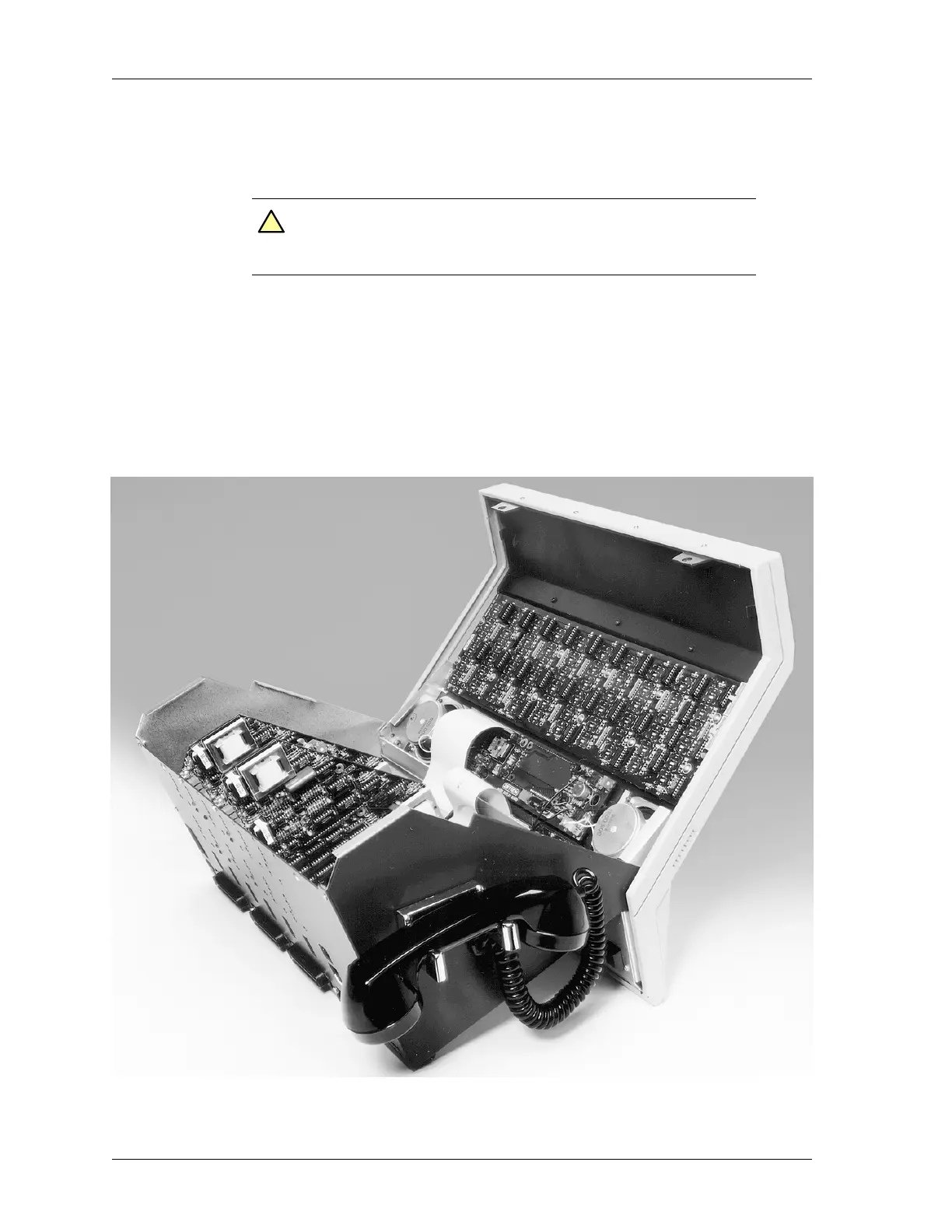
Figure 6 shows the view of the desktop console with the top opened. You will notice
several card slots designated J6-J12. Since the system is tested at the Zetron factory, you
will find the channel cards already plugged into the assigned slots. Slots J12-J7 are for
channel cards or Auxiliary I/O boards. J6 is for the Phone Patch card. On the back of the
unit are three 50-conductor male Amphenol-type plugs used to connect the Console to the
punch-down blocks and radios. These are designated J4 (channels 1-4), J3 (channels 5-8),
and J2 (channels 9-12).
Figure 6: A Model 4010 with its case open
Caution! Keep the front of the desktop unit on the tabletop, do not let
the front hang over a table edge. The console can be knocked
off balance onto the floor in this position.
!
 Loading...