H7016 User Manual
2-10
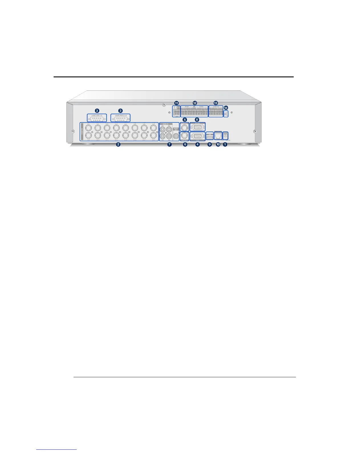
(2) REAR PANEL AND CONNECTION LOCATIONS
H7016
① Power supply connector
Connect the power supply to the DVR unit.
② Video Input
Connect camera co-axial cable output to the BNC connector
Channels locate in the order 1 to 8 from left to right.
The lower column is channels 9 to 16.
③ Video thru output (for 7016)
This loop thru output port can only be used for 7016 model.
Connect to loopback the saved video to other device on this port.
④ VGA Monitor Out
Connect to the VGA monitor on this port
⑤ MAIN Video Output
Connect to the main CCTV monitor on this port.
⑥ SPOT Monitor Output
Displays single channel and event triggered channels on a connected
SPOT monitor for more intensive monitoring.