118 CHAPTER 11: PORT ISOLATION CONFIGURATION
Displaying Port
Isolation
Configuration
After the above configuration, you can execute the display command in any view
to display the result of your port isolation configuration, thus verifying your
configuration.
Port Isolation
Configuration
Example
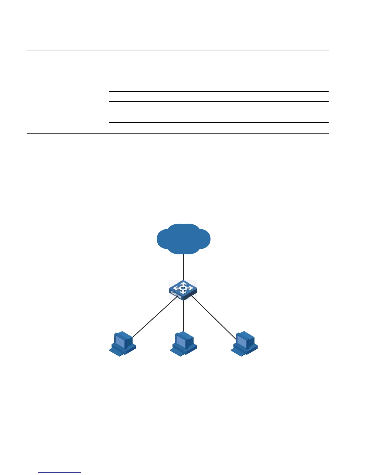
Network requirements
■ PC2, PC3 and PC4 connect to the switch ports Ethernet1/0/2, Ethernet1/0/3,
and Ethernet1/0/4 respectively.
■ The switch connects to the Internet through Ethernet1/0/1.
■ It is desired that PC2, PC3 and PC4 are isolated from each other so that they
cannot communicate with each other.
Network diagram
Figure 39 Network diagram for port isolation configuration
Configuration procedure
# Add Ethernet1/0/2, Ethernet1/0/3, and Ethernet1/0/4 to the isolation group.
<4210> system-view
System View: return to User View with Ctrl+Z.
[4210] interface ethernet1/0/2
[4210-Ethernet1/0/2] port isolate
[4210-Ethernet1/0/2] quit
[4210] interface ethernet1/0/3
[4210-Ethernet1/0/3] port isolate
[4210-Ethernet1/0/3] quit
Tabl e 76 Display port isolation configuration
Operation Command Description
Display information about
the Ethernet ports added to
the isolation group
display isolate port You can execute the display
command in any view.
Internet
PC 2
Eth1/0/1
Switch
Eth1/0/3
Eth1/0/4
PC 3
PC 4
Eth1/0/2