MSTP Configuration Example 183
Switch B are configured as the root bridges of spanning tree instance 1 and
spanning tree instance 3 respectively. Switch C is configured as the root bridge of
spanning tree instance 4.
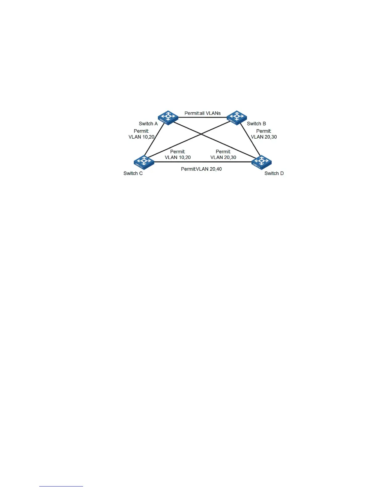
Network diagram
Figure 54 Network diagram for MSTP configuration
n
The word "permit" shown in Figure 54 means the corresponding link permits
packets of specific VLANs.
Configuration procedure
1 Configure Switch A
# Enter MST region view.
<4210> system-view
[4210] stp region-configuration
# Configure the region name, VLAN-to-MSTI mapping table, and revision level for
the MST region.
[4210-mst-region] region-name example
[4210-mst-region] instance 1 vlan 10
[4210-mst-region] instance 3 vlan 30
[4210-mst-region] instance 4 vlan 40
[4210-mst-region] revision-level 0
# Activate the settings of the MST region manually.
[4210-mst-region] active region-configuration
# Specify Switch A as the root bridge of spanning tree instance 1.
[4210] stp instance 1 root primary
2 Configure Switch B
# Enter MST region view.
<4210> system-view
[4210] stp region-configuration
# Configure the region name, VLAN-to-MSTI mapping table, and revision level for
the MST region.
[4210-mst-region] region-name example
[4210-mst-region] instance 1 vlan 10
[4210-mst-region] instance 3 vlan 30
[4210-mst-region] instance 4 vlan 40
[4210-mst-region] revision-level 0
# Activate the settings of the MST region manually.