Configuration Example 381
[DeviceB] display ntp-service sessions
source reference stra reach poll now offset delay disper
**************************************************************************
[12345]1.0.1.11 127.127.1.0 2 1 64 1 350.1 15.1 0.0
note: 1 source(master),2 source(peer),3 selected,4 candidate,5 configured
Total associations : 1
Configuring NTP
Symmetric Peer Mode
Network requirements
■ The local clock of Device A is set as the NTP master clock, with the clock
stratum level of 2.
■ Device C (a Switch 4210) uses Device A as the NTP server, and Device A works
in server mode automatically.
■ The local clock of Device B is set as the NTP master clock, with the clock
stratum level of 1. Set Device C as the peer of Device B.
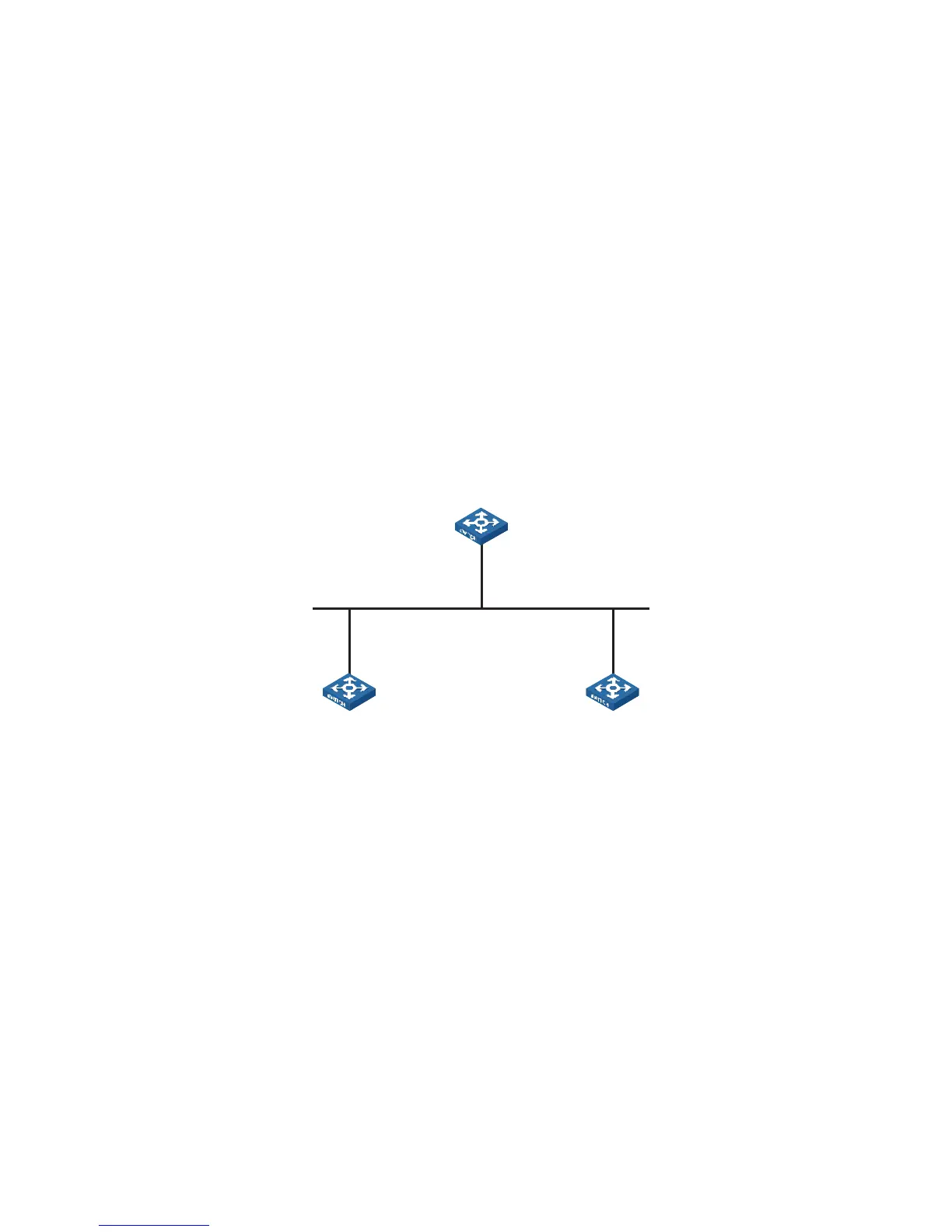
Network diagram
Figure 115 Network diagram for NTP peer mode configuration
Configuration procedure
1 Configure Device C.
# Set Device A as the NTP server.
<DeviceC> system-view
[DeviceC] ntp-service unicast-server 3.0.1.31
2 Configure Device B (after the Device C is synchronized to Device A).
# Enter system view.
<DeviceB> system-view
# Set Device C as the peer of Device B.
[DeviceB] ntp-service unicast-peer 3.0.1.33
Device C and Device B are symmetric peers after the above configuration. Device B
works in symmetric active mode, while Device C works in symmetric passive mode.
Because the stratum level of the local clock of Device B is 1, and that of Device C is
3, the clock of Device C is synchronized to that of Device B.
View the status of Device C after the clock synchronization.
[DeviceC] display ntp-service status
Clock status: synchronized
Device A
Device B Device C
3.0.1.31/24
3.0.1.32/24 3.0.1.33/24