384 CHAPTER 35: NTP CONFIGURATION
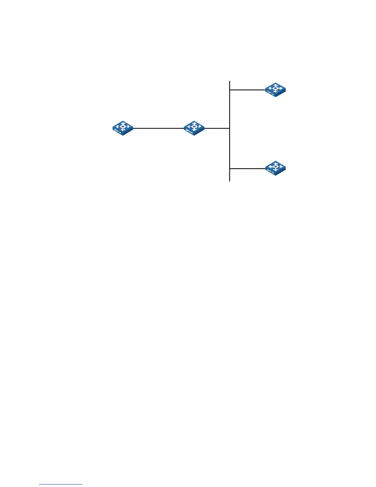
Network diagram
Figure 117 Network diagram for NTP multicast mode configuration
Configuration procedure
1 Configure Device C.
# Enter system view.
<DeviceC> system-view
# Set Device C as a multicast server to send multicast messages through
Vlan-interface2.
[DeviceC] interface Vlan-interface 2
[DeviceC-Vlan-interface2] ntp-service multicast-server
2 Configure Device A (perform the same configuration on Device D).
# Enter system view.
<DeviceA> system-view
# Set Device A as a multicast client to listen to multicast messages through
Vlan-interface2.
[DeviceA] interface Vlan-interface 2
[DeviceA-Vlan-interface2] ntp-service multicast-client
After the above configurations, Device A and Device D respectively listen to
multicast messages through their own Vlan-interface2, and Device C advertises
multicast messages through Vlan-interface2. Because Device A and Device C do
not share the same network segment, Device A cannot receive multicast messages
from Device C, while Device D is synchronized to Device C after receiving multicast
messages from Device C.
View the NTP status of Device D after the clock synchronization.
[DeviceD] display ntp-service status
Clock status: synchronized
Clock stratum: 3
Reference clock ID: 3.0.1.31
Nominal frequency: 100.0000 Hz
Actual frequency: 100.0000 Hz
Clock precision: 2^18
Clock offset: 198.7425 ms
Root delay: 27.47 ms
Vlan -int2
1. 0. 1. 31/ 24
Vlan-int2
3.0.1.31/24
Vlan-int2
3.0.1.32/24
Device A Device B
Device C
Device D