Aprisa SR+ User Manual 1.11.1
Monitoring
The Terminal, Serial, Ethernet, Radio and User Selected Monitored Parameter results have history log views
for both Quarter Hourly and Daily.
Monitored parameter data is accumulated into 2 sets:
• 15 minutes of data, for 96 readings for the last 24 hours
• 24 hours of data, for 31 readings for the last 31 days.
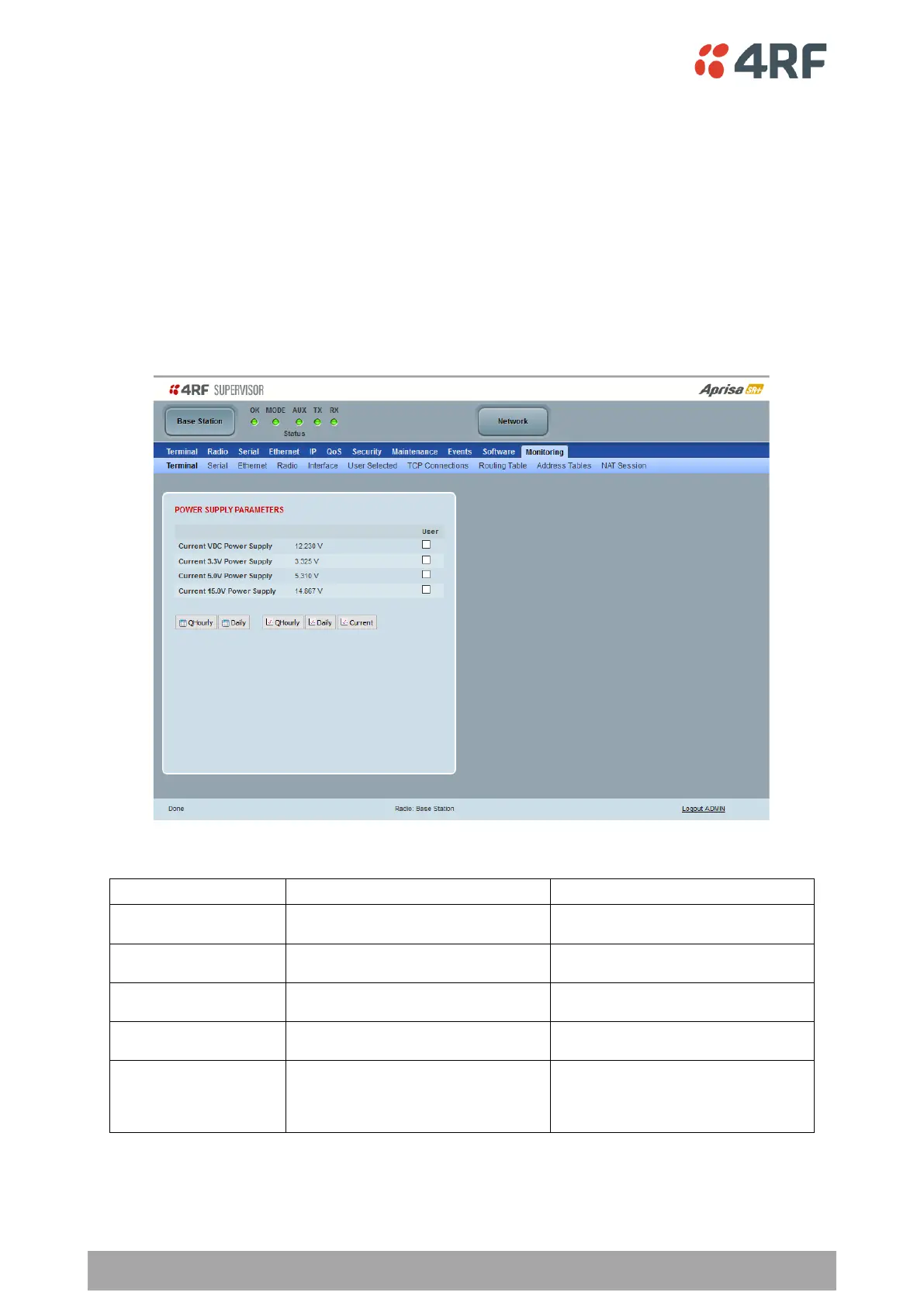
Monitoring > Terminal
This page displays the current radio internal and external input source radio power supply voltage diagnostic
parameters.
POWER SUPPLY PARAMETERS
Parameter to show the current power
supply input voltage
Current 3.3 Volts Power
Supply
Parameter to show the current 3.3 volt
power rail voltage
Current 5.0 Volts Power
Supply
Parameter to show the current that the
current 5.0 volt power rail voltage
Current 7.2 Volts Power
Supply
Parameter to show the current that the
current 7.2 volt power rail voltage
Current 15 Volts Power
Supply
Parameter to show the current that the
current 15 volt power rail voltage.
The 15 volt power supply is used to power
the transmitter driver and power amplifier.
320, 400 and 450 MHz
14.5 to 15.3 VDC
135, 220, 896 and 928 MHz
12.7 to 13.5 VDC