Aprisa SR+ User Manual 1.11.1
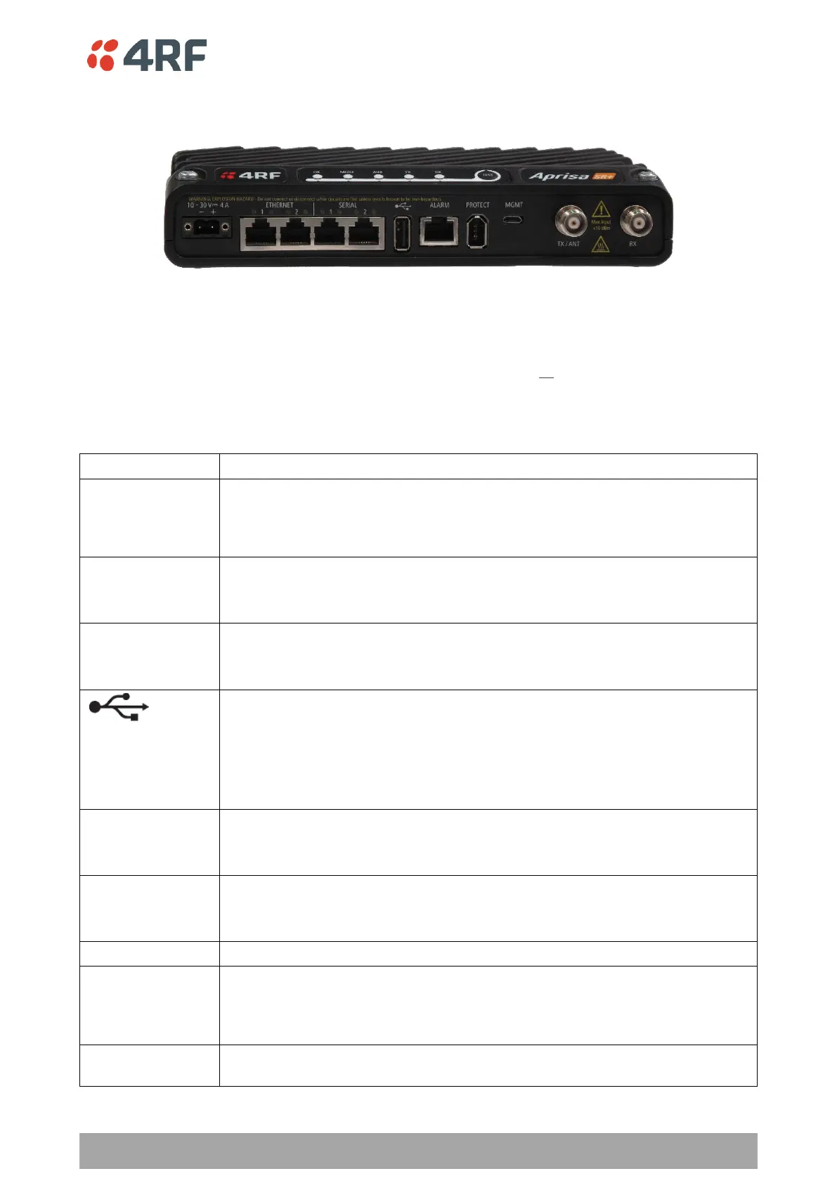
Front Panel Connections
Example; 2 Ethernet ports and 2 RS-232 serial ports - see ‘Data Interface Ports’ on page 401 for the other
interface port options.
2 Ethernet ports and 2 RS-232 serial ports
All connections to the radio are made on the front panel. The functions of the connectors are (from left to
right):
+10 to +30 VDC (negative ground) DC power input using Molex 2 pin male screw
fitting connector.
AC/DC and DC/DC power supplies are available as accessories. See ‘External
Power Supplies’ on page 85.
Integrated 10Base-T/100Base-TX layer-3 Ethernet switch using RJ45 connectors.
Used for Ethernet user traffic and product management.
See ‘Ethernet > Port Setup’ on page 169.
Two ports of RS-232 serial using RJ45 connectors.
Used for RS-232 asynchronous user traffic.
See ‘Serial > Port Setup’ on page 151.
Host Port using a USB standard type A connector.
Used for software upgrade and diagnostic reporting and optional: 1x RS-232
asynchronous port with USB to RS-232 converter.
See ‘Software Upgrade’ on page 441 and ‘Maintenance > General’ on page 261.
Also used to access the radio Command Line Interface (CLI). A USB converter to
RS-232 convertor will be required to connect to a PC.
Alarm Port using a RJ45 connector.
Used for two alarm inputs and two alarm outputs.
See ‘Hardware Alarms Interface’ on page 485.
Management Port using a USB micro type B connector.
Used to access the radio Command Line Interface (CLI).
See ‘Connecting to the CLI via the Management Port’ on page 390.
Protect port. Used for Protected Station operation.
TNC, 50 ohm, female connector for connection of antenna feeder cable for half
duplex RF operation or the Transmit connection to an external duplexer for full
duplex RF operation or to an external filter.
See ‘Coaxial Feeder Cables’ on page 77.
TNC, 50 ohm, female connector for the Receive connection to an external
duplexer for full duplex RF operation or to an external filter.