Operation Manual / 4 Product description / A130-M.. - A145-M..
Page 92 /
© Copyright 2017 ABB. All rights reserved.
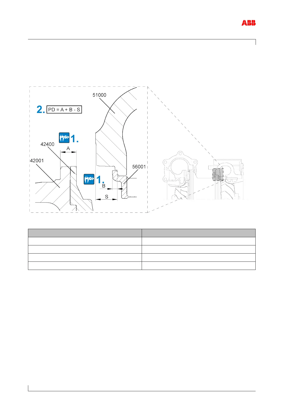
8.12 Nozzle ring compression PD
For the nozzle ring (56001) to be fixed during operation, it must be clamped between the heat
shield (42400) and the turbine casing (51000).
Figure 44: Nozzle ring compression PD
A130 -0.15 ... 0.15
A135 -0.16 ... 0.16
A140 -0.16 ... 0.16
A145 -0.16 ... 0.16
Table 39: Permitted nozzle ring compression PD
42001 Bearing casing 51000 Turbine casing
1. Measure dimensions A, B, and S on cleaned surfaces.
2. Calculate compression (PD).
If the calculated value (PD) lies outside the specified range, contact an ABB Turbocharging
Service Station.