Operation Manual / 4 Product description / A130-M.. - A145-M..
Page 12 /
© Copyright 2017 ABB. All rights reserved.
2.2 Removing the turbocharger
The gas outlet casing (61001) can remain fitted in the exhaust gas pipe if the locking nuts are
accessible. Otherwise the complete turbocharger unit including gas outlet casing must be re-
moved.
Disconnect all pipes according to the instructions of the enginebuilder.
If present: Loosen and remove the compressor wheel cooling connection. Close the com-
pressor wheel cooling opening with a screw plug (01).
If present: Disconnect the plug to the speed sensor (86505) and secure the rolled-up cable
on the turbocharger. This protects the plug from being crushed.
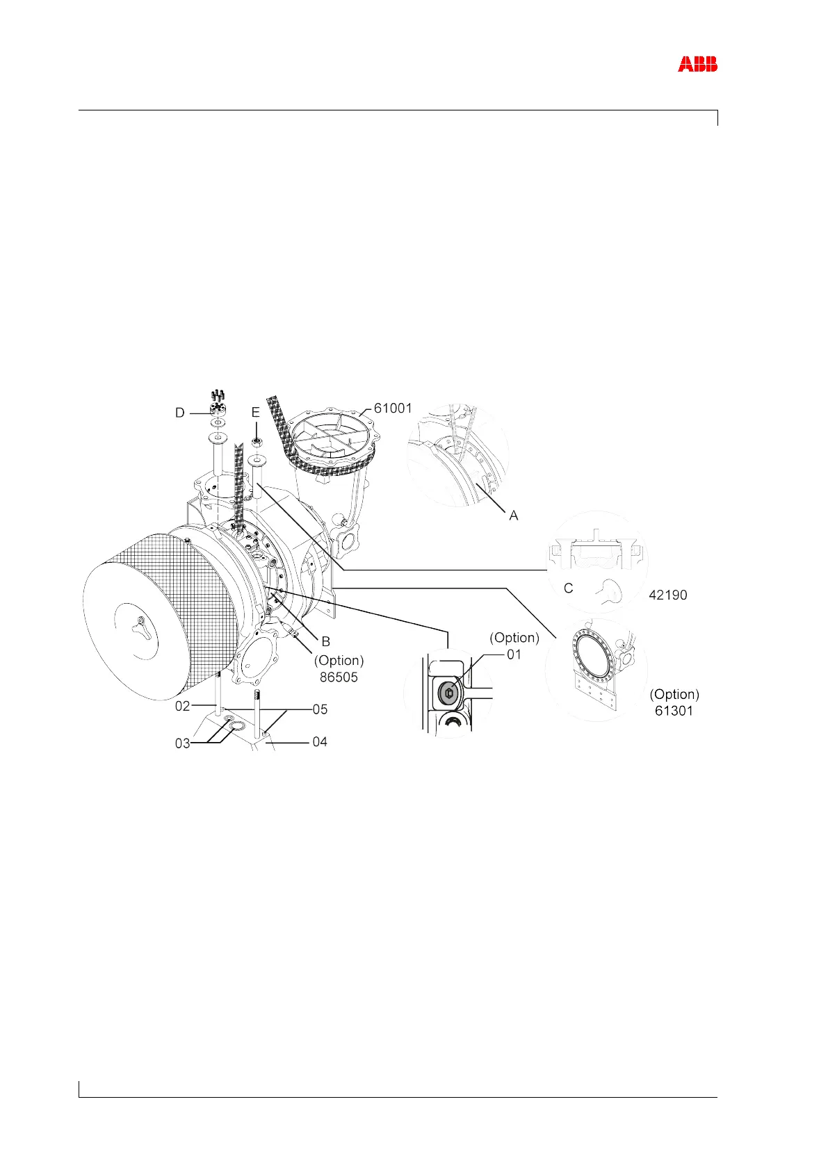
Figure 6: Removing the turbocharger
A Oil-cooled bearing casing D Clamping nut
B Water-cooled bearing casing E Standard nut
C Position of expansion sleeves
Treat the stud (02) and nut with penetrating oil on the thread and let it work in.
If present: Detach the support (61301) from the engine support.
Depending on the bracket version (04), two positioning pins (05) can be used for positioning
and safeguarding against wrong fitting of the turbocharger. Therefore the turbocharger must
always be removed from and installed on the bracket vertically.