Operation Manual / 4 Product description / A130-M.. - A145-M..
Page 16 /
© Copyright 2017 ABB. All rights reserved.
2.3 Installing the turbocharger
2.3.1 Inserting gaskets
Gaskets that are forgotten, damaged or improperly inserted will lead to oil
leaks.
Always use new gaskets and insert them carefully into the slot.
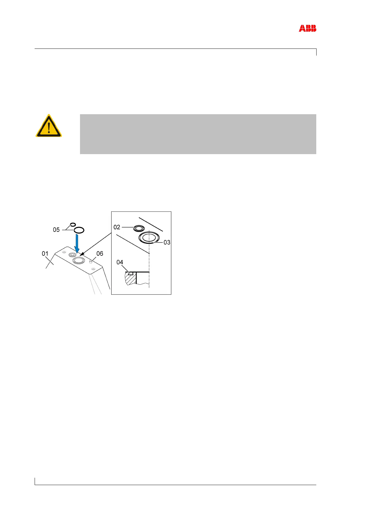
The oil is supplied (02) and drained (03) through the bracket (01).
The necessary sealing is provided by O-rings. The O-rings are not included in the ABB Turbo
Systems scope of delivery.
Figure 9: Inserting gaskets into the bracket
01
Bracket 04
Slot for O-ring
02
Oil supply 05
O-rings
03
Oil drain 06
Pin (optional)
Pin (06) as installation safety device
Turbochargers can have an oil inlet either on their right or left side; the oil inlet position can be
different for the turbocharger fitted on the left and on the right engine bank.
A pin can be installed in every support as an installation safety device to prevent inadvertent
incorrect fitting. This pin fits into the respective slot on the foot of the bearing casing. Instruc-
tions of the enginebuilder must be observed.