Operation Manual / 4 Product description / A130-M.. - A145-M..
Page 99 /
© Copyright 2017 ABB. All rights reserved.
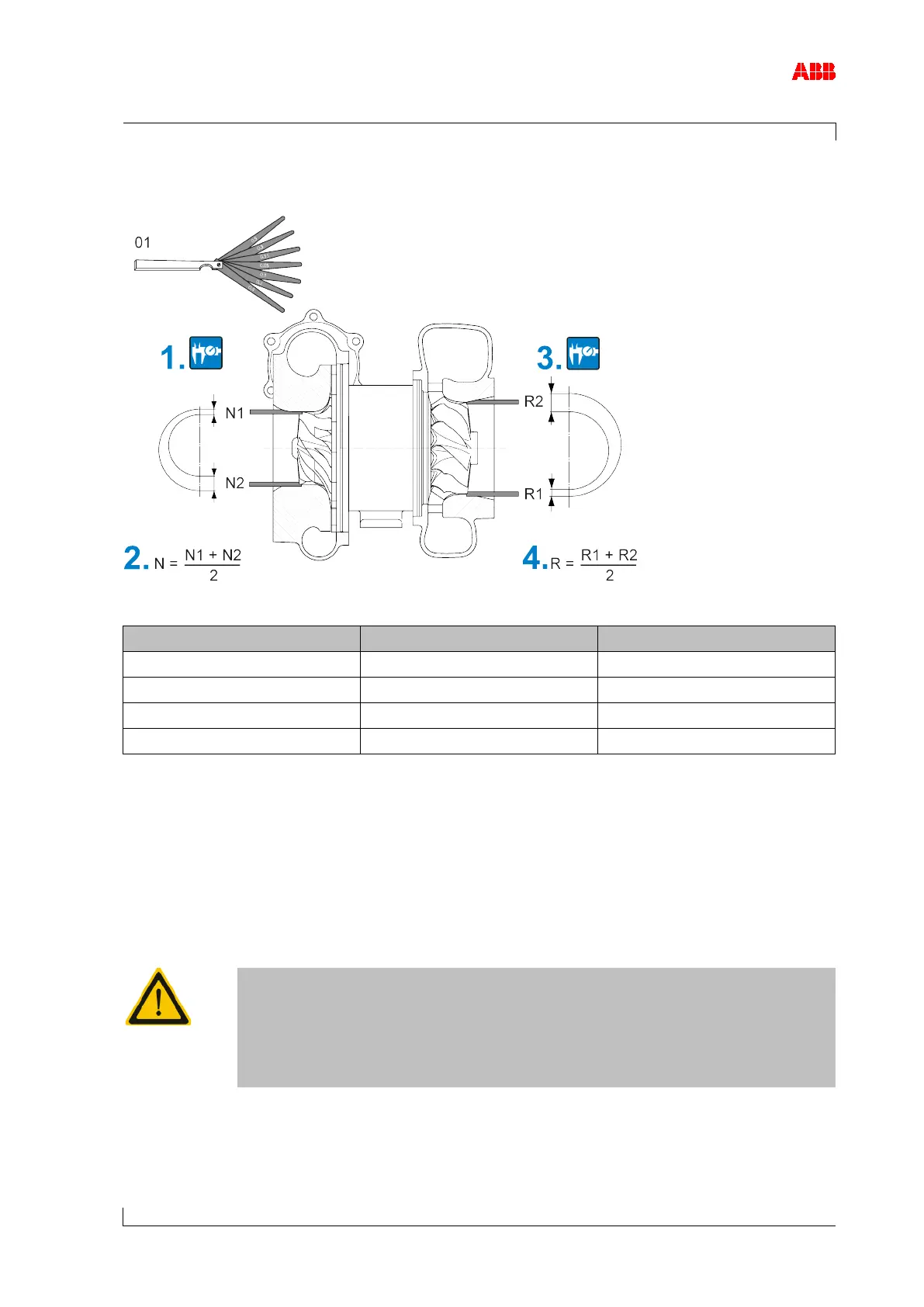
8.16 Radial clearances N and R
Figure 50: Measuring clearances N and R
A130 0.26 ... 0.60 0.45 ... 0.70
A135 0.34 ... 0.70 0.51 ... 0.85
A140 0.45 ... 0.90 0.64 ... 1.00
A145 0.56 ... 0.95 0.76 ... 1.20
Table 43: Permissible clearances N and R
1. Push the feeler gauges (01) into the gap such that there is no clearance. The upper direc-
tion (N1) and lower direction (N2) must be covered simultaneously.
2. Calculate clearance N and compare it with the permissible values in the table.
3. Push the feeler gauges (01) into the gap such that there is no clearance. The upper direc-
tion (R2) and lower direction (R1) must be covered simultaneously.
4. Calculate clearance R and compare it with the permissible values in the table.
Clearances outside the tolerance
Serious damage to engines or property can be caused by clearances out-
side the tolerance and excessively worn parts.
Have the components assessed and, if necessary, replaced by an ABB
Turbocharging Service Station.