ABB EQmatic
Planning and application
96 2CDC512090D0202 | QA/S x.yy.1
What is M-Bus?
M-Bus (Meter-Bus) is a European standard for remotely reading gas, water, heat or electricity meters.
The M-Bus interface is designed for communication over two-wire lines. This bus satisfies the special
requirements for remotely powered or battery-operated meters. The meters send the collected
measured values and data to a common master for further processing on request.
Bus principle
The M-Bus is based on the master-slave principle.
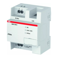
Master = level converter (e.g. QA/S 3.xx.1 Energy Analyzer)
Slave = M-Bus device/meter (e.g. ABB electricity meter from the A and B series, water meter, heat
meter, gas meter, etc., with M-Bus interface).
Up to 250 addresses (M-Bus devices) can be processed and polled in an M-Bus installation.
The QA/S 3.xx.1 Energy Analyzer supports up to 16 or 64 meters, depending on the device type.
The M-Bus master polls the individual bus addresses. The bus address is either the primary address
1 – 250 or the 8-digit secondary address (generally the device’s meter number or serial number).
The corresponding slaves/meters respond with a data telegram. The data received from the
slaves/meters are saved in the M-Bus master (e.g. QA/S 3.xx.1 Energy Analyzer) for further
processing.
The primary address 0 is preset in the factory for M-Bus devices. The primary address must be
assigned in the meter.
Transmission speed
The M-Bus is generally designed for speeds from 300 to 9600 baud. ABB meters from the A and B
series can communicate at speeds of 2400 - 9600 baud. The speed must be set in the meter.
Polarity
The M-Bus interface is protected against polarity reversal, i.e. the wires of the cable used can be
interchanged.
Topology
The M-Bus supports different bus topologies. The cables should be kept as short as possible.
A combination of star, tree and linear structure is typically used to minimize the cable lengths.
However, a ring structure is not advisable because a single fault can cause the entire system to
become faulty. Furthermore, a ring structure makes troubleshooting more difficult.