32 Electrical installation
Connecting the module to the PROFIBUS network
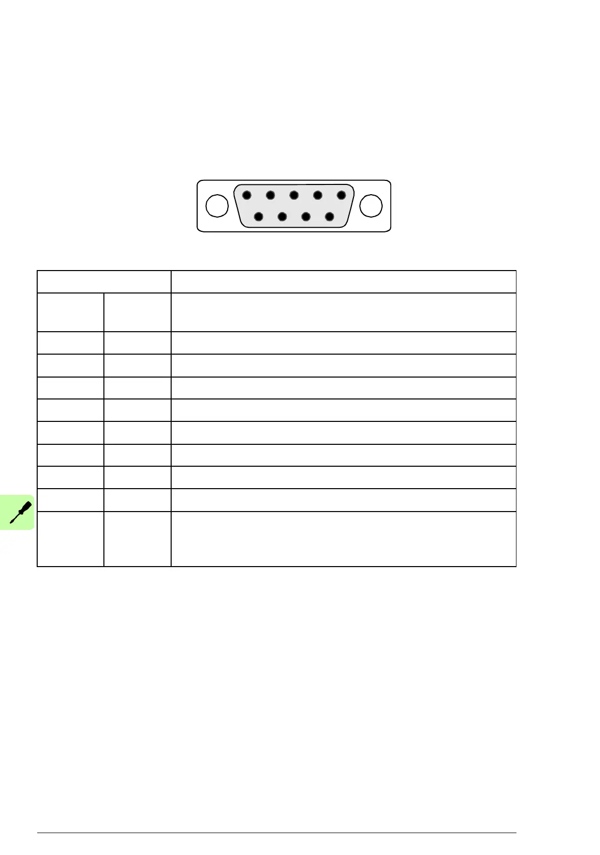
Connect the bus cable to connector X1 on the adapter module.
The connector pin allocation described below follows the
PROFIBUS standard.
X1 Description
1 SHLD Alternate cable shield connection. Connected to
connector housing.
2 Not used
3 B Data positive (Conductor 1 in twisted pair)
4RTS
1)
Request to send
5 GND_B Isolated ground
6+5V_B
2)
Isolated 5 V DC voltage supply (30 mA max.)
7 Not used
8 A Data negative (Conductor 2 in twisted pair)
9 Not used
Housing SHLD PROFIBUS cable shield. Internally connected to
GND_B via an RC filter and directly to CH_GND
(chassis).
1)
RTS is used in some equipment to determine the direction of
transmission. In typical applications, only the line A, line B and shield are
used.
2)
+5V_B and GND_B are used for bus termination.