NoteAction
Art no. is specified in Required
equipment on page 243.
Apply the lifting tool, motor axis 1, 4, 5 to the motor.4
Connect to connector R2.MP1
• +: pin 2
• -: pin 5
In order to release the brake, connect the 24 VDC
power supply.
5
Make sure the motor is turned the
correct way, that is connection of
motorcable as shown in the figure
Location of motor on page 242.
Fit the motor, making sure the motor pinion is
properly mated to gearbox of axis 1.
6
Make sure the motor pinion does
not get damaged!
Fit the clutch on the pinion on the motor.7
M10 x 40, tightening torque: 50
Nm.
Secure the motor with its four attachment screws
and plain washers.
8
Disconnect the brake release voltage.9
Reconnect all connectors beneath the motor cover.10
Make sure the cover is tightly
sealed!
Refit the cable gland cover at the cable exit with its
two attachment screws.
11
Make sure the cover is tightly
sealed!
Refit the motor cover with its four attachment
screws.
12
Pendulum Calibration is described
in Operating manual - Calibration
Pendulum, enclosed with the calib-
ration tools.
Recalibrate the robot!13
Axis Calibration is described in
Calibrating with Axis Calibration
method on page 319.
General calibration information is
included in section Calibration on
page 305.
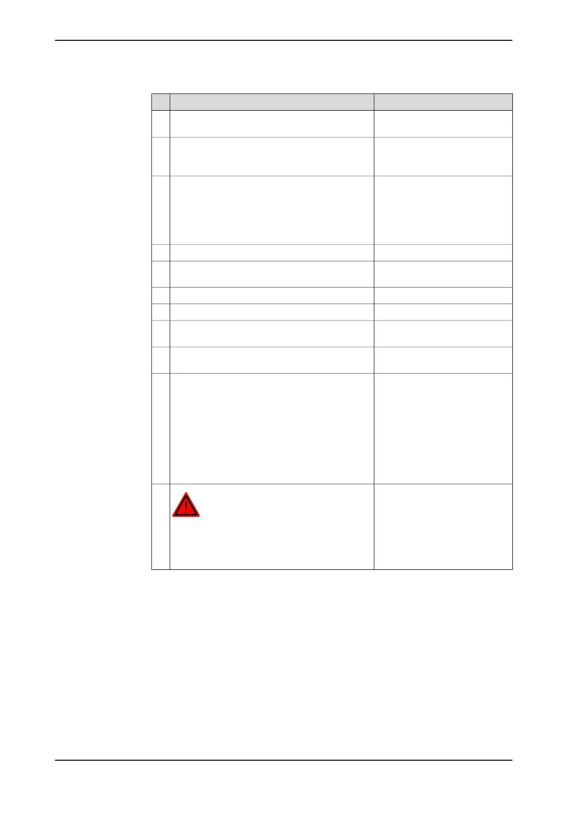
DANGER
Make sure all safety requirements are met when
performing the first test run. These are further de-
tailed in the section First test run may cause injury
or damage on page 27.
14
246 Product manual - IRB 6620
3HAC027151-001 Revision: T
© Copyright 2006-2018 ABB. All rights reserved.
4 Repair
4.6.1 Replacement of motor, axis 1
Continued