NoteAction
xx0600003034
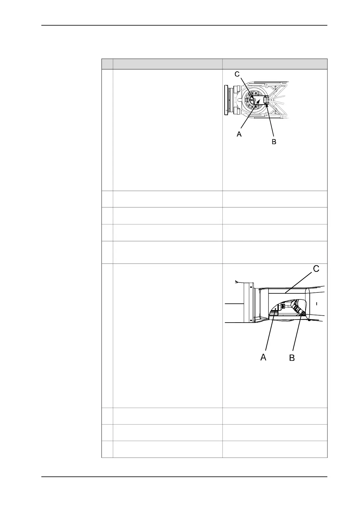
Remove the cable holder in the wrist unit
by unscrewing the three attachment screws.
Two of the attachment screws (M6x16) are
visibly located at the rear of the cable hold-
er. The third screw (M4x12) is located at the
bottom of the cable holder, securing the
carrier.
6
• A : Cable holder
• B : Attachment screws M6x16, 8.8
(2 pcs)
• C : Attachment screw M4x12, 8-
A2F (securing the carrier)
Remove the back cover motor, axis 6 by
removing its attachment screws.
7
Shown in the figure Location of cable
harness on page 196
Pull out the cabling R2.MP6 and R2.FB6
from motor axis 6 .
8
Shown in the figure Location of cable
harness on page 196
Disconnect all connectors at motor axis 6
R2.MP6 and R2.FB6.
9
Loosen the cable bracket in the upper arm
tube by undoing its two attachment screws
on top of the tube.
10
xx0700000072
Disconnect the two connectors (R2.FB5 and
R2.MP5) inside the tube.
11
Parts:
• A: Motor axis 5 with connectors
R4.FB5 and R4.MP5
• B: Connectors R2.FB5 and R2.MP5
• C: Upper arm tube
Remove eventual cable straps from the
harness.
12
Remove the cover motor axis 4 by removing
its attachment screws.
13
Shown in the figure Location of cable
harness on page 196
Disconnect all connectors at motor axis 4
(R2.MP4, R2.FB4).
14
Continues on next page
Product manual - IRB 6660 199
3HAC028197-001 Revision: S
© Copyright 2007-2018 ABB. All rights reserved.
4 Repair
4.3.3 Replacement of cable harness, upper end
Continued
 Loading...


