NoteAction
xx1000001101
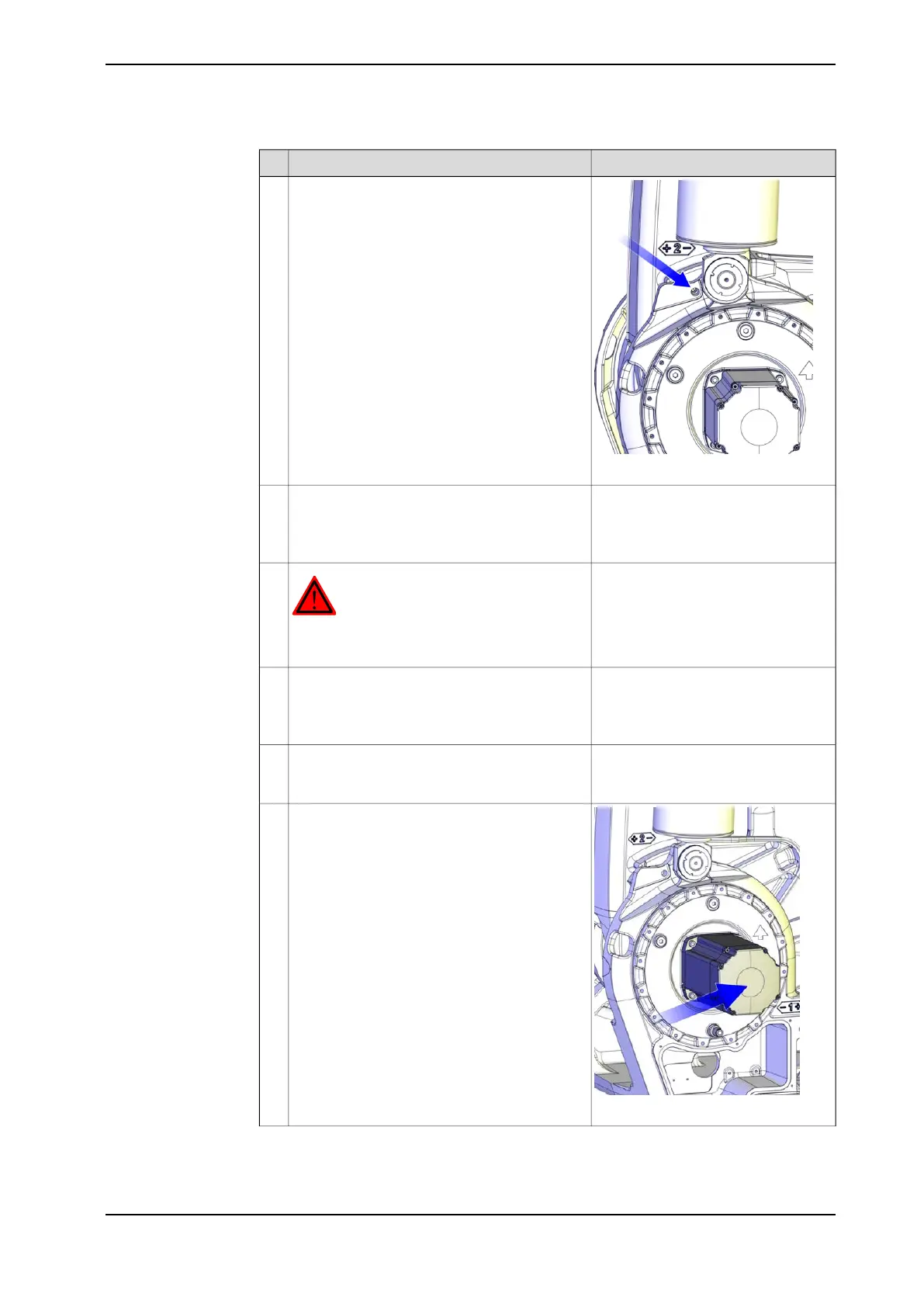
Run the robot to a position close enough to its
calibration position, to allow the lock screw to
be inserted into the hole for lock screw.
2
See figure above.Lock the lower arm by inserting the lock screw
into the hole of the frame.
3
This is done in order to secure axis 2 from col-
lapsing when gearbox axis 2 is being removed.
DANGER
Turn off all electric power, hydraulic and pneu-
matic pressure supplies to the robot!
4
Secure the upper arm with roundslings in an
overhead crane.
5
This is done in order to secure axis 3 from col-
lapsing when gearbox axis 3 is being removed.
See section
• Draining, axes 2 and 3 on
page 151
Drain the oil from gearbox.6
xx1000001102
Remove the motor cover.7
Continues on next page
Product manual - IRB 6660 283
3HAC028197-001 Revision: S
© Copyright 2007-2018 ABB. All rights reserved.
4 Repair
4.6.2 Replacing motors, axes 2 and 3
Continued
 Loading...


