Mechanical installation 37
Consider this when installing heat-generating components (such as other drives and
braking resistors) nearby.
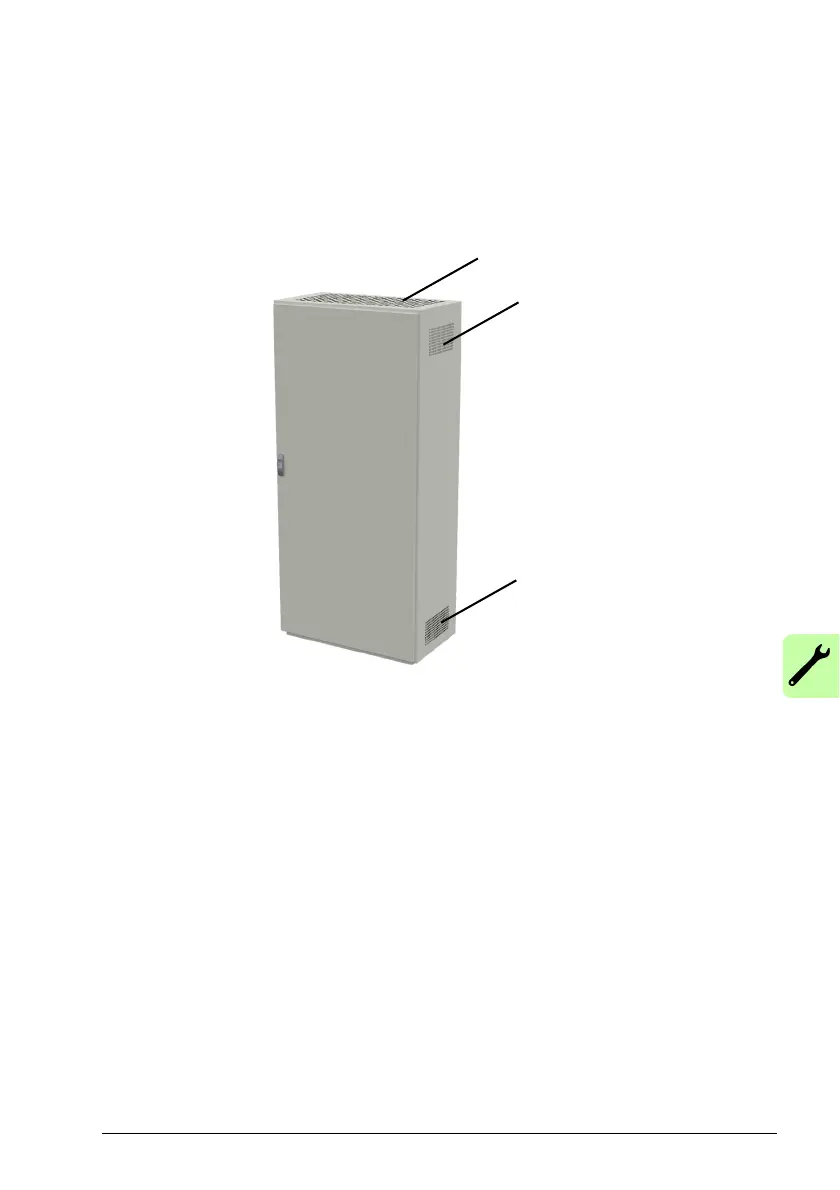
The drawing below shows two typical cabinet cooling solutions. The air inlet is at the
bottom of the cabinet, while the outlet is at the top.
Air inlet
Air outlet
Air outlet
Arrange the cooling of the drives so that the requirements given in chapter Technical
data are met:
• Cooling air flow. Note that the values in Technical data apply to continuous
nominal load. If the load is less than nominal, less cooling air is required.
• Allowed ambient temperature.
Make sure the air inlets and outlets are sufficient
in size. Note that in addition to the
power loss of the drive, the heat dissipated by cables and other additional equipment
must also be ventilated.
The internal cooling fans of the drives are
usually sufficient to keep the component
temperatures low enough in IP22 cabinets.
In IP54 cabinets, thick filter
mats are used to prevent water splashes from entering
the cabinet. This entails the installation of additional cooling equipment, such as a hot
air exhaust fan.
The installation site must be sufficiently ventilated.