Electrical installation: input / output 89
Encoder 1 input
Encoder 1 is an extra incremental encoder input channel and can be used to set up
dual-encoder control system or be connected to a master encoder. It comes from fast
digital inputs 1 and 2 on connector X3.
The incremental encoder signal type:
• 24 V DC signal levels
• Logic levels: “0” < 2 V, “1” > 12 V
• A/B single ended, no Z index
• User power supply: 24 V DC
Encoder 2 input
Encoder 2 is extra incremental encoder input channel and can be used to set up dual-
encoder control system or be connected to a master encoder. The encoder input is
5V differential line driver (RS422).
The incremental encoder signal type:
• RS422 A/B/Z differential
• Max. input frequency A / B: 2 MHz
• Power supply: 5.5 V DC
See application note AN00262 for more information about dual encoder control.
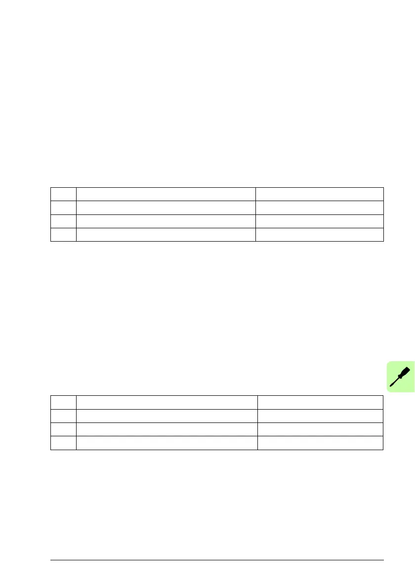
No. Feedback type Parameter
1 Rotary incremental encoder without Halls ENCODERTYPE(1)=0
2 Linear incremental encoder without Halls ENCODERTYPE(1)=1
3 Step & Direction inputs ENCODERMODE(1)=4
No. Feedback type Parameter
1 Rotary incremental encoder without Halls ENCODERTYPE(2)=0
2 Linear incremental encoder without Halls ENCODERTYPE(2)=1
3 Step & Direction inputs ENCODERMODE(2)=4