Electrical installation: input / output 85
is set to match the input resolution. In all other cases there is a propagation delay of
up to 125 µs.
Use one of the following methods to con
figure X7 as an encoder output:
• In Mint WorkBench, choose the Drive Setup tool an
d proceed to the Motor
Feedback page. In the Simulated Encoder Output 0 area, click in the Encoder
source channel drop down and choose one of the encoder sources 0, 1, or 2 as
described above. Proceed to the end of the wizard and follow the instructions to
save the changed parameter.
• In Mint WorkBench, choose the Parameters too
l and expand the Encoder family.
Click the EncoderOutChannel entry, then click the value next to
EncoderOutChannel (Encoder Channel 0). Choose one of the encoder sources 0,
1, or 2 as described above. On the menu, choose Tools, Store Drive Parameters.
• In Mint WorkBench, choose the Edit & Deb
ug tool. In the Command window enter
the command: ENCODEROUTCHANNEL(0)=n, where n is 0, 1, or 2, as described
above. On the menu, choose Tools, Store Drive Parameters.
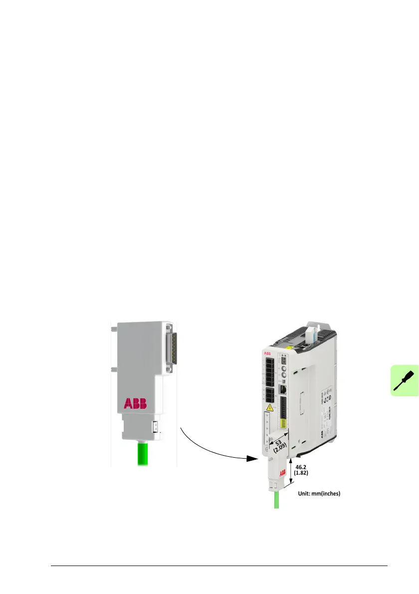
OPT-MF-201 Resolver adapter
The optional resolver adapter OPT-MF-201 allows a motor with resolver feedback to
be connected to the MicroFlex e190. See page 181 for details.