84 Electrical installation: input / output
The step and direction inputs are both differential and must be controlled from a
RS422 differential source. Single-ended connections cannot be used.
• The A channel pins (1 & 6) are used as the step input. The step frequency
controls the speed of the motor.
• The B channel pins (2 & 7) are used as the di
rection input. The state of the
direction input controls the direction of motion.
• The Z channel input is not used.
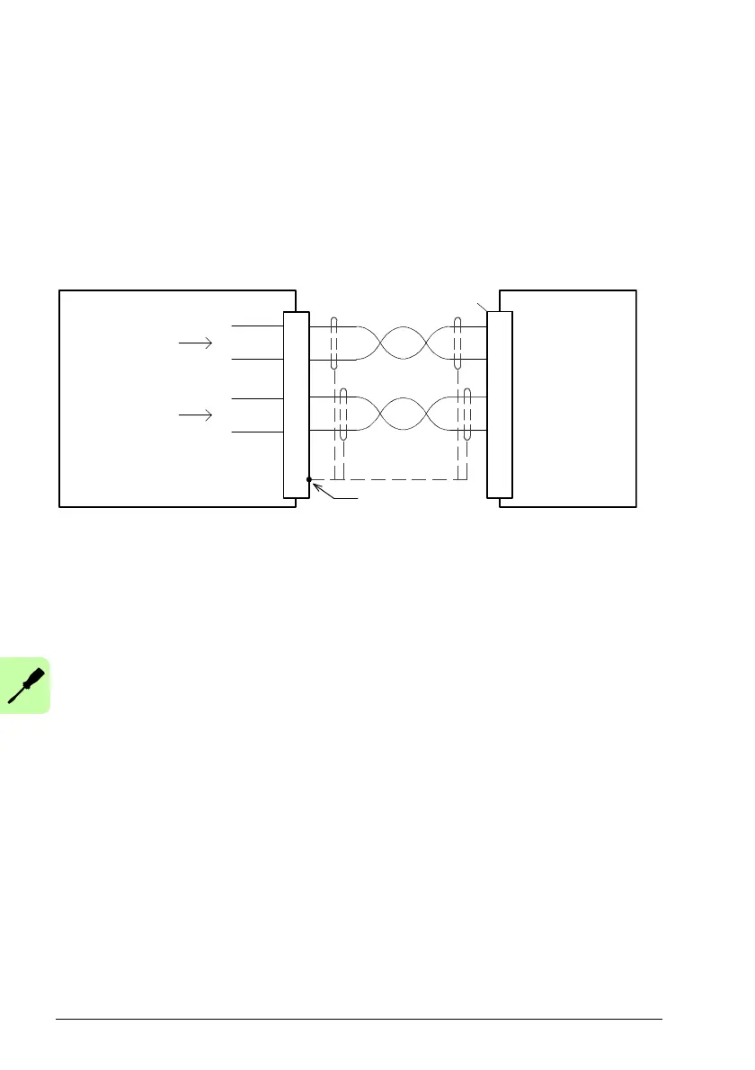
Step / direction inputs - typical connections from a PLC/controller:
PLC/controller
Step+
Connect shields at
one end only.
Step
output
Dir
output
Twisted pairs
Dir+
MicroFlex e190
Shield
Step-
Dir-
Note: The inputs should be use shielded twisted pair cable with an overall shield.
Connect the input signals correctly according to the pin assignment for connector X7.
Encoder output mode
Optionally, connector X7 can be configured as an encod
er output (encoder output 0).
This automatically enables the extra incremental encoder input on connector X8,
which then becomes encoder input 2 (see page 81). When operating as an encoder
output, X7 can be connected to the encoder i
nput of a motion controller to provide
position feedback. The A/B outputs are a pair of synthesized pulse trains with a 50%
duty cycle, 90 degrees out of phase. The ENCODEROUTCHANNEL Mint keyword is
used to define the source signal that will be output at X7:
• -1 = (Default) No encoder source assign
ed, X7 operates as an encoder input.
• 0 = Encoder 0, the primary encoder input on X8.
• 1 = Encoder 1, the encoder input formed by digi
tal inputs DI1 and DI2 when they
are set to behave as an encoder input (see Special functions on inputs DI1 & DI2
on page 66).
• 2 = Encoder 2, the extra incremental encoder interface on X8.
The frequency of the A/B outputs is varied a
ccording to the source signal, and can be
scaled using the ENCODEROUTRESOLUTION Mint keyword. The output at X7 is
identical to the input at X8, with no propagation delay, provided the output resolution