Manual Power Quality Filter PQFM The PQF-Manager user interface 111
If the hardware lock is engaged, the logging function cannot be started nor reset (Cf.
Section 7.6)
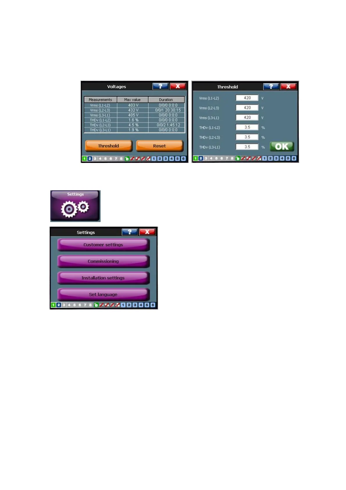
Figure 82 shows an example in which the network voltage between L1 and L2 is
monitored. The nominal network voltage is assumed to be 400 V. The threshold was
initially set at 1000 V and is changed to 420 V.
Figure 82: Example of the Min/Max logging function (4-W mode)
7.9 The ‘Settings’ menu
The ‘Settings’ menu [/Welcome/Settings] has four main levels:
− Thecustomer levelwhich allows the user to set up the typical user requirements
such as harmonic filtration settings, the reactive power settings, sets up the
digital inputs and outputs and defines the programmable warnings and alarms.
At this level, the user can also change the temperature unit used by the system.
The customer level is accessed through [/Welcome/Settings/Customer set.]
− Thecommissioning level which allows the commissioning engineer to set up the
equipment according to the customer’s installation. Typical parameters that
need to be entered are the network voltage and frequency, the CT parameters
and a derating factor that needs to be applied when the installation is at great
height above sea level or in conditions where excessive ambient temperatures are
present. At the commissioning level the possibility also exists to set up the user’s
requirements for harmonic filtration and reactive power compensation. The
commissioning level is accessed through [/Welcome/Settings/Commissioning].