Manual Power Quality Filter PQFM Mechanical design and installation 39
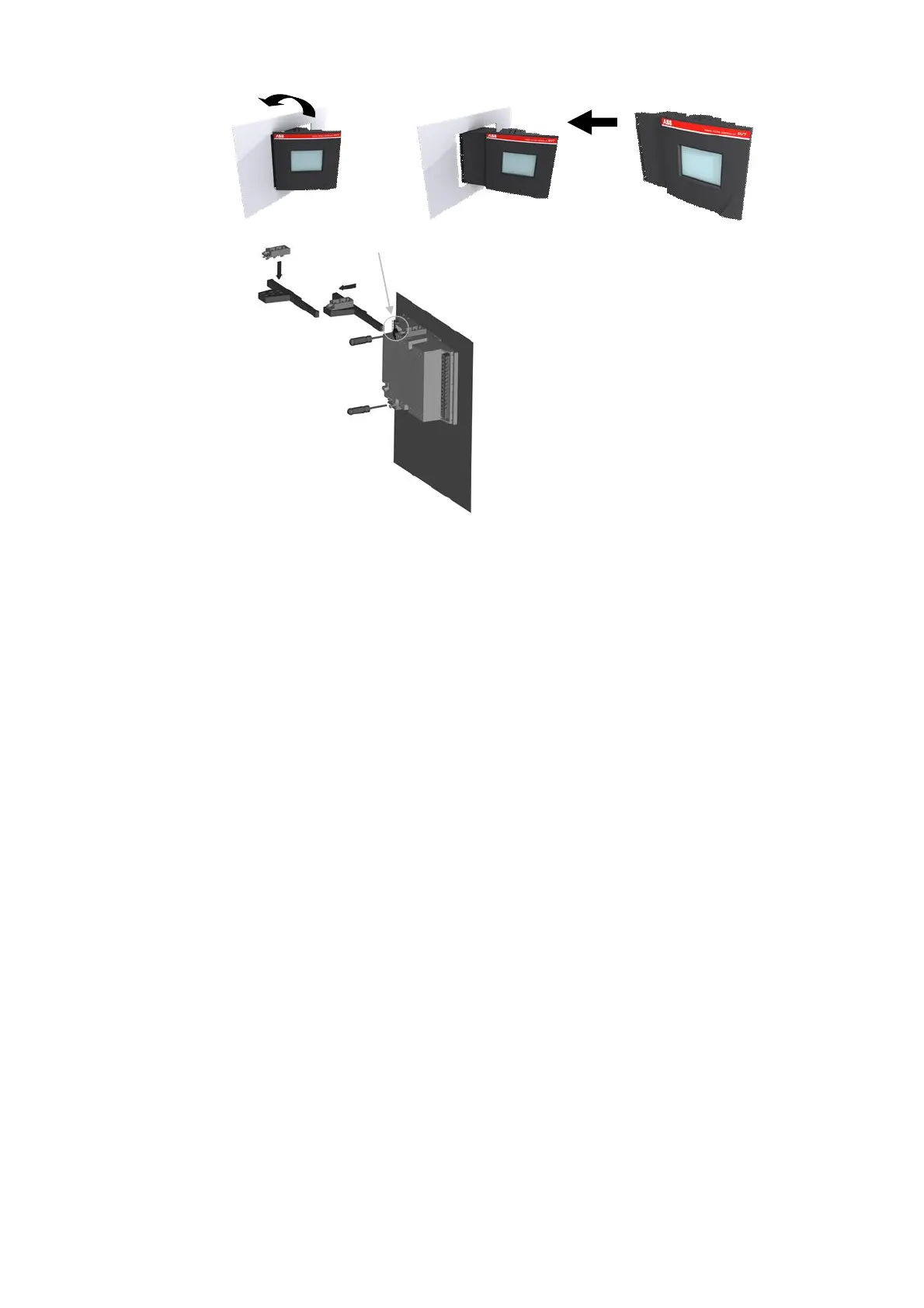
Step 2
(b)
Step 3
Step 4(c)
(e)Step 5
the bottom Mounting
Bracket.
Figure 21: Mechanical installation of the PQF-Manager
Step 1: Slide the PQF-Manager (a) perpendicularly to the Capacitor Bank Cubicle (b).
Step 2: Rotate the PQF-Manager to insert it into the Capacitor Bank Cubicle.
Note: cut out dimensions are 138 x 138 mm.
Step 3: Insert the Mounting Bracket (c) in the corresponding Fixation Holes (d) of the
PQF-Manager.
Step 4: Pull the Mounting Bracket backwards.
Step 5: Turn the Screw (e) into the Mounting Bracket and tighten until the PQF-Manager
is secured in place.
Once the PQF-Manager has been installed, it has to be connected electrically (see Section
6.2).
5.6 Mechanical interconnection of PQFM cubicles
This section explains how to mechanically interconnect PQFM units (master-master,
master-slave or slave-slave). Figure 22 outlines the steps to undertake to mechanically
interconnect two PQFM units.