Manual Power Quality Filter PQFM The PQF-Manager user interface 167
WARNING: The secondary circuit of a loaded CT must never be opened. Otherwise
extremely high voltages may appear at its terminals which can lead to physical danger
or destruction of the CT.
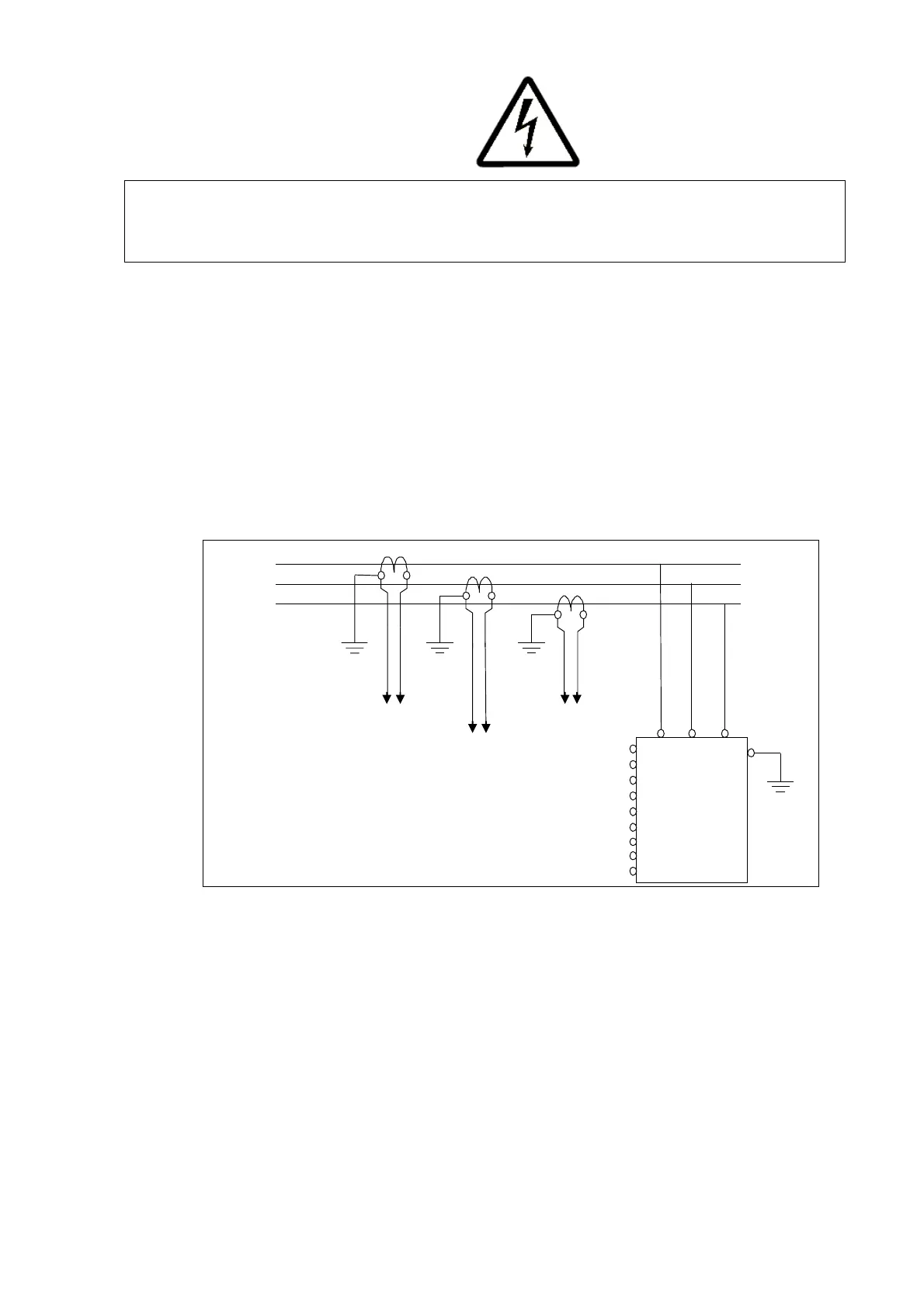
8.6.2.1 PQF connection diagram
Figure 91 shows the standard connection diagram for the PQF (Cf. Section 7.9.1). It must
be noted that:
− L1, L2 and L3 rotation must be clockwise.
− The CTs must be on the supply (line) side of the PQF.
− The CT monitoring a phase must be connected to the filter CT terminal dedicated
to the same phase.
− One secondary terminal of the CT must be earthed.
L2
X21.2
X21.3
X21.4
X21.5
X21.6
X21.7
X21.8
X21.9
To X21.1/X21.2
To X21.4/X21.5
K = P1, L = P2, k = S1, l = S2
Figure 91: Basic CT connection diagram
It is also seen that terminal X21.1 and X21.2 are related to the CT located in phase L1,
terminal X21.4 and X21.5 are related to the CT located in phase L2 and terminal X21.7 and
X21.8 are related to the CT located in phase L3.
For multi-unit filters, the following diagram is applicable: