190 Operating instructions Manual Power Quality Filter PQFM
Operation as
programmed
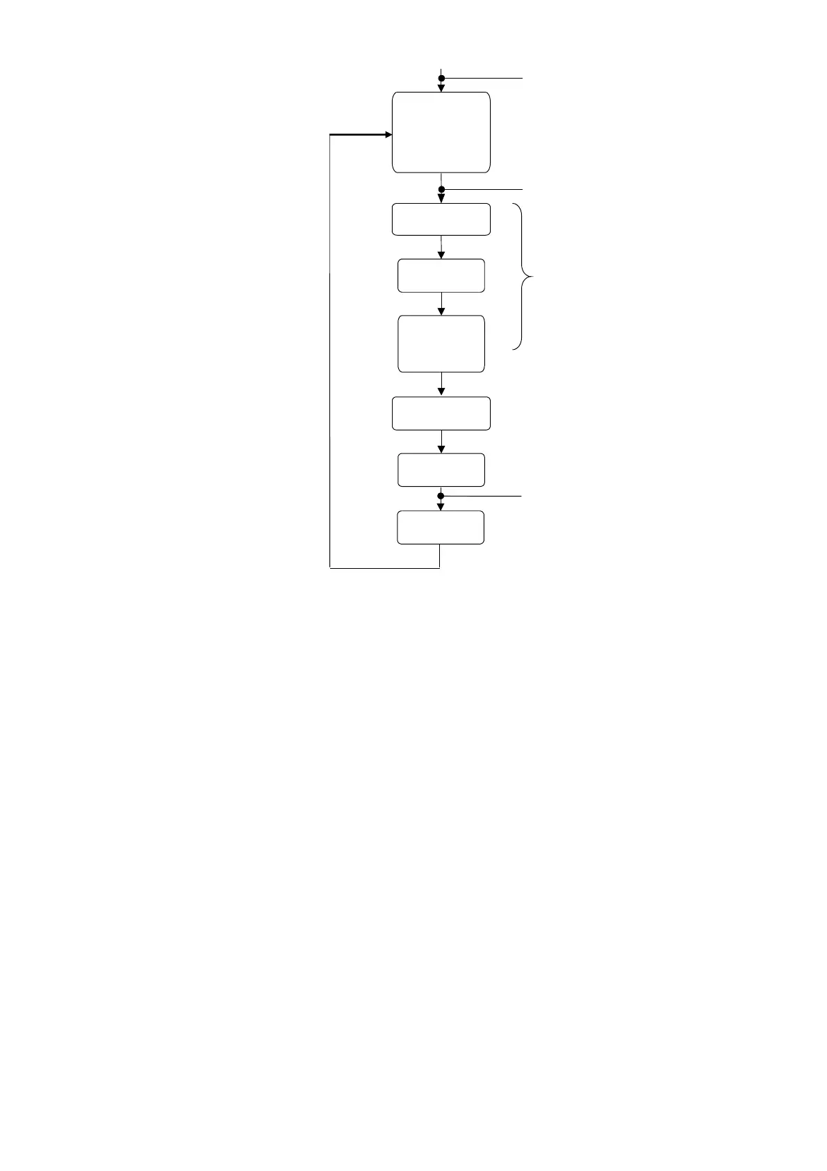
Close MC
fan(s)
running
Network
identification
Start-up sequence
Open MC
Stop filter
Start filter
and DC
capacitors
charging
auxiliaries
Figure 102: Filter operation sequence when no fault is present
The DC bus also incorporates discharge resistors that can discharge the DC bus in 25
minutes.
9.3 Modifying the user requirements
Providing that the filter locks have not been engaged, the user can change the customer
settings to better suit his needs. These settings can be accessed in the PQF-Manager
menu [/Welcome/Settings/Customer set.].
The user requirements can be divided into the following categories:
− Setting up the filter mode, the harmonic requirements and the reactive power
requirements. Refer to Section 7.9.1.1 for detailed information on these topics.
− Setting up alarms, warnings and digital I/O. The digital I/O allows configuration of
the filter to operate in remote control mode etc. Refer to Section 7.9.1.4 for detailed
information on these topics.
Advanced user requirements have to be set up in the ‘installation settings’ menu
([/Welcome/Settings/Installation set.]). These advanced functions include:
− The autorestart function (after power outage).
− The standby function to switch off the IGBTs when the load requirement is low.
− The system clock setup.