66 Electrical design and installation Manual Power Quality Filter PQFM
6.10.6 CT locations for the case of feeding transformer and backup generator
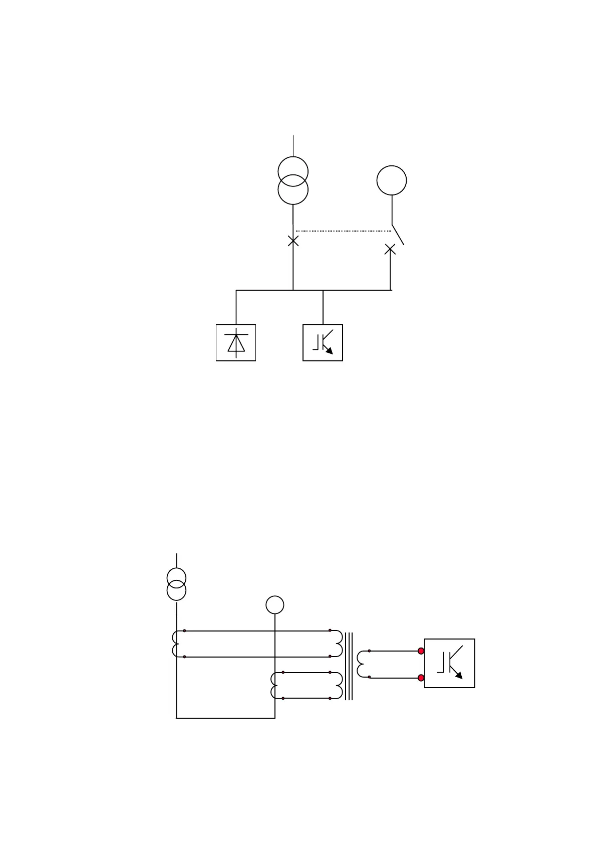
Many installations are fitted with backup generators to ensure the proper operation of
the installation in case of a mains supply outage.
A typical configuration is given in Figure 46.
G
LOAD
PQF
Figure 46: Single line diagram of an installation with a backup generator
The CT connection must be such that the active filter works whatever the type of supply:
generator or transformer-MV network.
For each phase, one CT is installed in the transformer branch and one in the generator
branch. Those two CTs must be identical (X / 5 A) and must be connected to a
summation CT rated 5+5 / 5 A.
The CT ratio to be programmed in the filter is: 2⋅X/5. Figure 47 gives the corresponding
connection diagram per phase.
S1, k
S2, l
S1, k
S2, l
P1
P2
P1
P2
S2
k
L
PQF
P1, K
P2, L
P1, K
P2, L
Figure 47: CT connections for the case of a feeding transformer with backup generator
(to be done for each phase)