64 Electrical design and installation Manual Power Quality Filter PQFM
The CT ratio to be programmed in the filter is: 2X/5 where X is the primary side current
rating of the main measurement CTs (CT1 and CT2 in Figure 42 above).
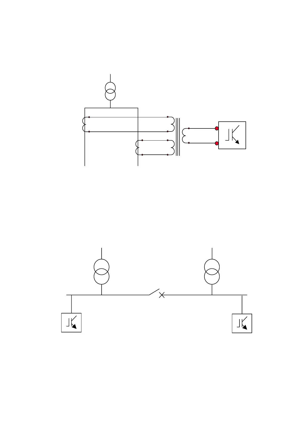
The connection diagram of the main measurement CTs to the summation CTs and from
the summation CTs to the filter terminals is represented in Figure 43. This diagram has
to be implemented for the three phases.
S1, k
S2, l
S1, k
S2, l
P1
P2
P1
P2
S1
S2
k
l
PQF
Side A Side B
P1, K
P2, L
P1, K
P2, L
Figure 43: CT connections for the case of connections between CT1, CT2 , the summation CT
and the PQF for one phase
6.10.5 CT locations for the case of two independent feeding transformers
Two independent transformers (the tie is normally open) feed two different sets of
loads. One active filter is connected to each LV busbar. The system may also have to work
in degraded mode, i.e. the tie is closed and only one transformer feeds the whole LV
system. This case is illustrated in Figure 44.
PQFPQF
T1 T2
Figure 44: Case of two independent feeding transformers
By connecting the CTs as described in Figure 45 it is possible to filter the harmonics and
to correct the power factor under the aforementioned conditions.