108 The PQF-Manager user interface Manual Power Quality Filter PQFM
7.8.2.3.1Waveforms
The filter current waveforms for all phases for the unit selected with the ‘Select unit’
option. The graph layout is similar to the one of the voltages (Figure 78). All waveforms
are synchronized with the rising edge zero crossing of the voltage V (L1-N) (4-W mode)
or V (L1-L2) (3-W mode).
7.8.2.3.2Spectrum
The filter current spectrum for all phases (3-W mode) and the neutral current spectrum
(4-W mode) in chart format for the unit selected with the ‘Select unit’ option. The chart
layout is similar to the one of the voltages (Figure 79) but the values are expressed in
absolute terms.
7.8.2.3.3Harmonic table
The filter current spectrum for all phases (3-W mode) and the neutral current spectrum
(4-W mode) in table format for the unit selected with the ‘Select unit’ option. The table
layout is similar to the one of the voltages (Figure 64) but only absolute current values
are shown.
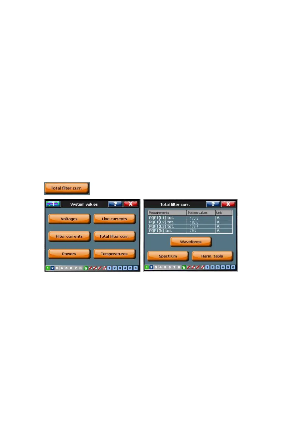
7.8.2.4 Total filter currents
Refer toTable 43 for an explanation of the parameters.
PQF Irms in table format for the complete filter system.
7.8.2.4.1Waveforms
The filter current waveforms for all phases for the complete filter system. The graph
layout is similar to the one of the voltages (Figure 78). All waveforms are synchronized
with the rising edge zero crossing of the voltage V (L1-N) (4-W mode) or V (L1-L2) (3-W
mode).
7.8.2.4.2Spectrum
The filter current spectrum for all phases (3-W mode) and the neutral current spectrum
(4-W mode) in chart format for the complete filter system. The chart layout is similar to
the one of the voltages (Figure 79) but the values are expressed in absolute terms.
7.8.2.4.3Harmonic table