84 Electrical design and installation Manual Power Quality Filter PQFM
Figure 57). Any digital input can be configured to act as the deciding factor for switching
between the main and auxiliary settings. Moreover, both normal and inverse logic can be
used to drive the digital inputs.
Note that in a multi-unit filter system in which more than one master system is present,
the digital inputs of all masters have to be set up and cabled in the same way to obtain
full redundancy.
The electrical requirements of the digital inputs are as discussed in Chapter 12.
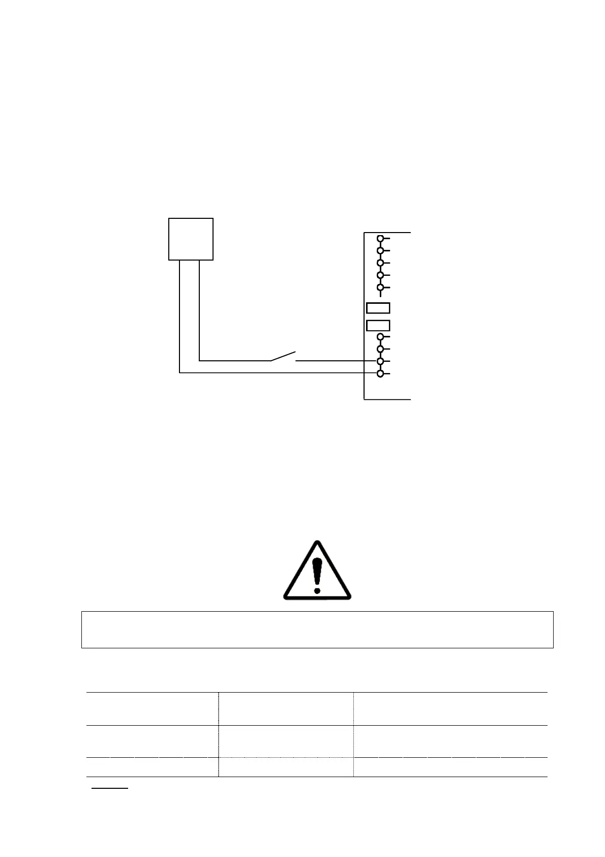
Figure 64 gives an example of how to implement the main/auxiliary control switching
functionality on Digital Input 2. It is assumed that normal control logic is used.
switching between main
and auxiliary filter settings
supply
3
4
(a)
Digital input 2
(15-24Vdc)
(a)
Left hand terminal block when looking from rear, counting from top to bottom
Figure 64: Example of how to cable the 2
nd
digital input of the PQF-Manager for main/auxiliary
control switching functionality
When implementing the function described above, please note that according to the
setup done with the PQF-Manager for the input considered, the filter may behave
differently.Table 33 shows the filter behavior as a function of the PQF-Manager settings.
WARNING: If a function is assigned to a digital input, the same function must never be
assigned to the other digital input. Otherwise the filter may behave erratically.
Table 33: Filter behavior as a function of the PQF-Manager settings for
main/auxiliary switching
digital input
input
Vhigh applied to digital input
Activ. Main
used
Main settings are used
Auxiliary settings are used
: Vlow = 0 Vdc, Vhigh = 15