Manual Power Quality Filter PQFM Electrical design and installation 63
6.10.4 CT locations for the case of global compensation – transformer busbar
not accessible
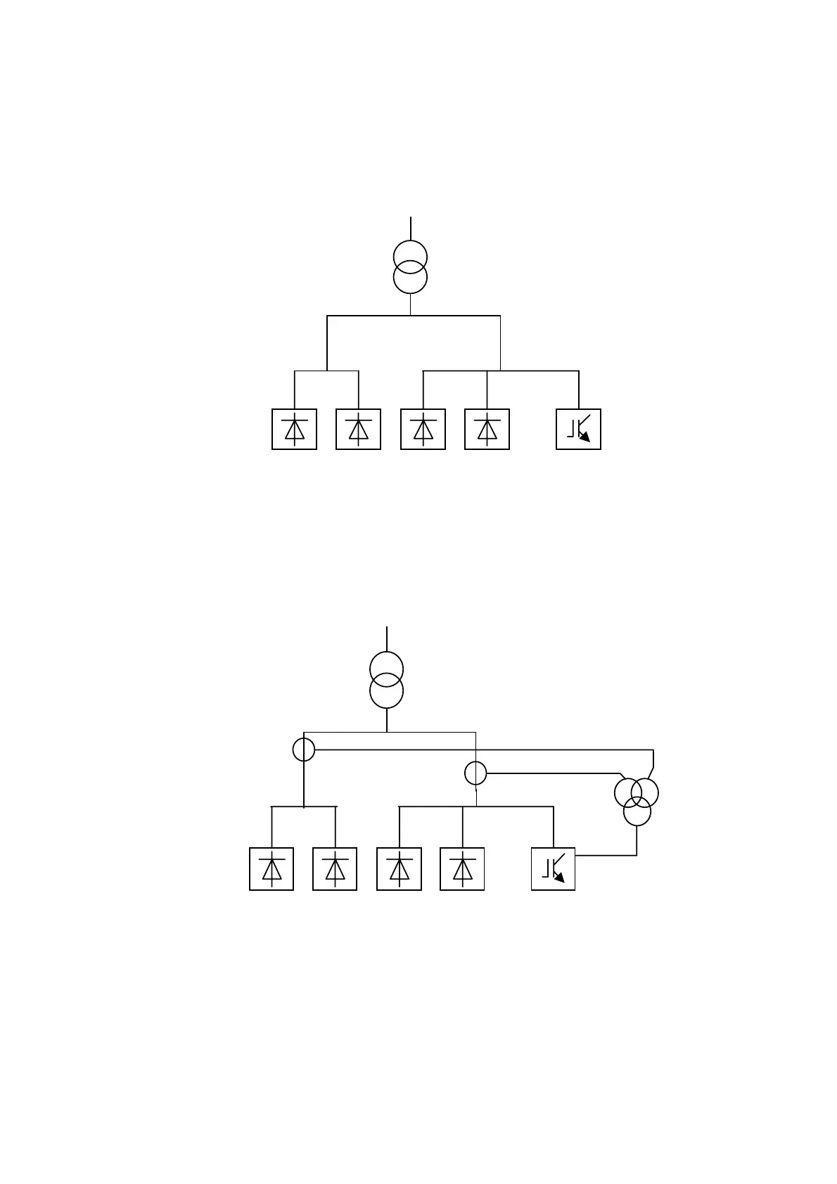
The active filter is required to filter the loads of side A and side B (Cf. Figure 41) but the
transformer busbar is not accessible. As a result, the CTs cannot be installed in a central
position.
LOADS LOADS
(Side A) (Side B)
PQF
Figure 41: Case of multiple loads and transformer busbar not accessible
For this configuration, three CTs (one per phase) have to be installed on side A and on
side B (i.e. in total 6 CTs). Those CTs will then feed 3 summation CTs (one per phase) that
are connected to the active filter. This CT topology is represented in Figure 41.
LOADS
(Side A)
LOADS
(Side B)
PQF
(one per phase)
Primary 1: 5 A
Primary 2: 5A
Secondary: 5A
CT 1 (one per phase)
Primary: X
Secondary: 5A
CT 2 (one per phase)
Primary: X
Secondary: 5A
Figure 42: CT connections for the case of multiple loads and transformer busbar not accessible
(to be done for each phase)
The CTs installed in each phase of side A and B (CT1 and CT2) must be identical (X/5A)
and feed a summation CT whose secondary is 5A (5+5/5A). The summation CT is then
connected to the active filter in accordance with Section 6.10.1. A total of 3 summation
CTs (one per phase) must be used.